Low head water turbine

a low-head water turbine and low-efficiency technology, applied in the direction of rotary piston engines, conventional hydropower generation, tidal stream/damless hydropower, etc., can solve the problems of low-head water turbines, low efficiency, and sections of small rivers having low head or drop

Inactive Publication Date: 2005-04-12
SALMON RIVER PROJECT LTD THE
View PDF6 Cites 22 Cited by
  • Summary
  • Abstract
  • Description
  • Claims
  • Application Information

AI Technical Summary

Problems solved by technology

Traditionally, low head water turbines have been of an open type, as exemplified for example by conventional water wheels, and have had extremely low efficiency.
This has meant, for example, that sections of small rivers having a low head or drop, have been unsuitable for generation of hydro electric power.
Such arrangements have necessitated large dams, construction of flumes and the like, necessitating, often, massive capital expenditure.

Method used


Image

  • Low head water turbine
  • Low head water turbine
  • Low head water turbine

Examples


Embodiment Construction

In the following description, similar features in the drawings have been given similar reference numerals.

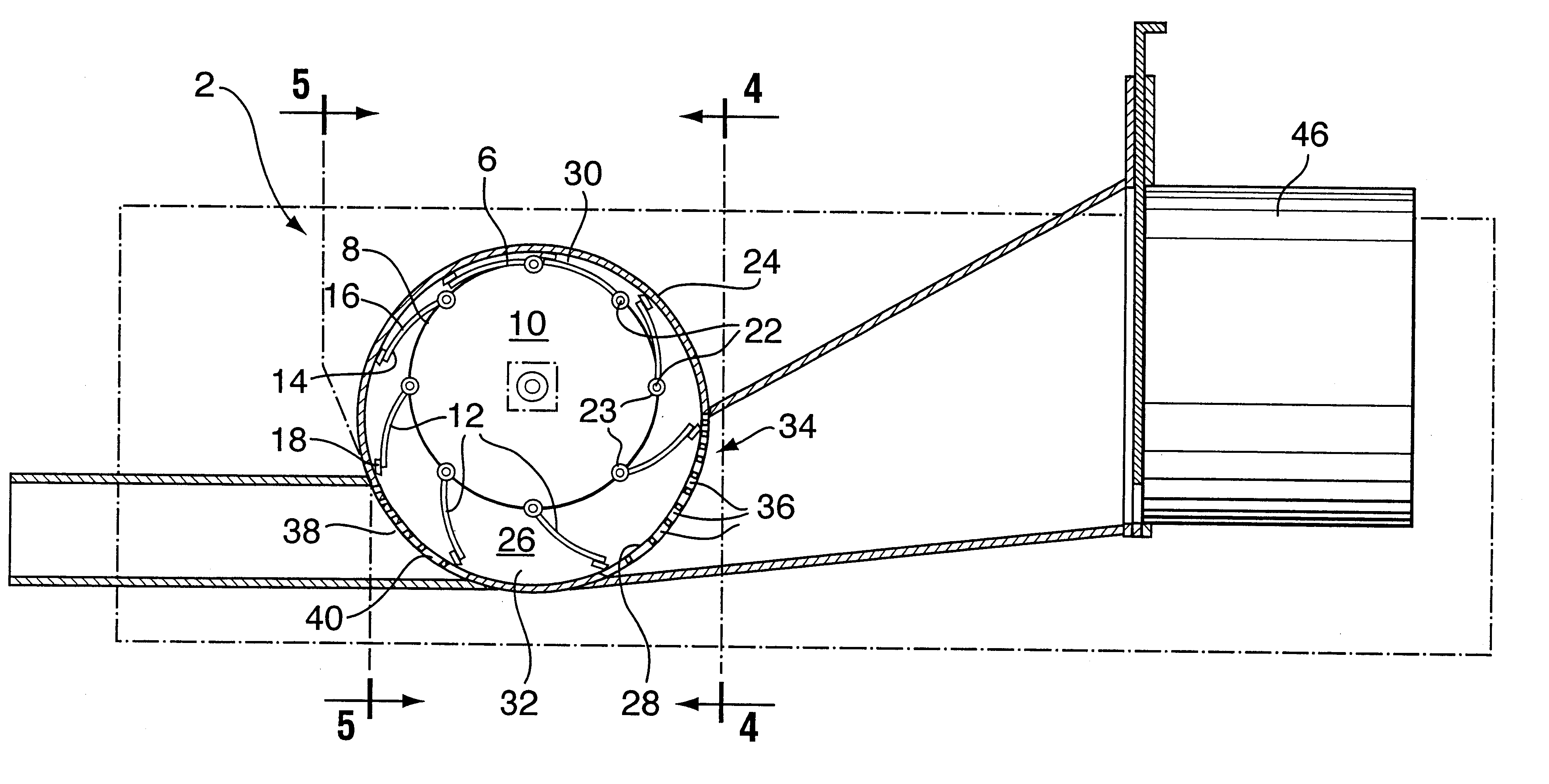
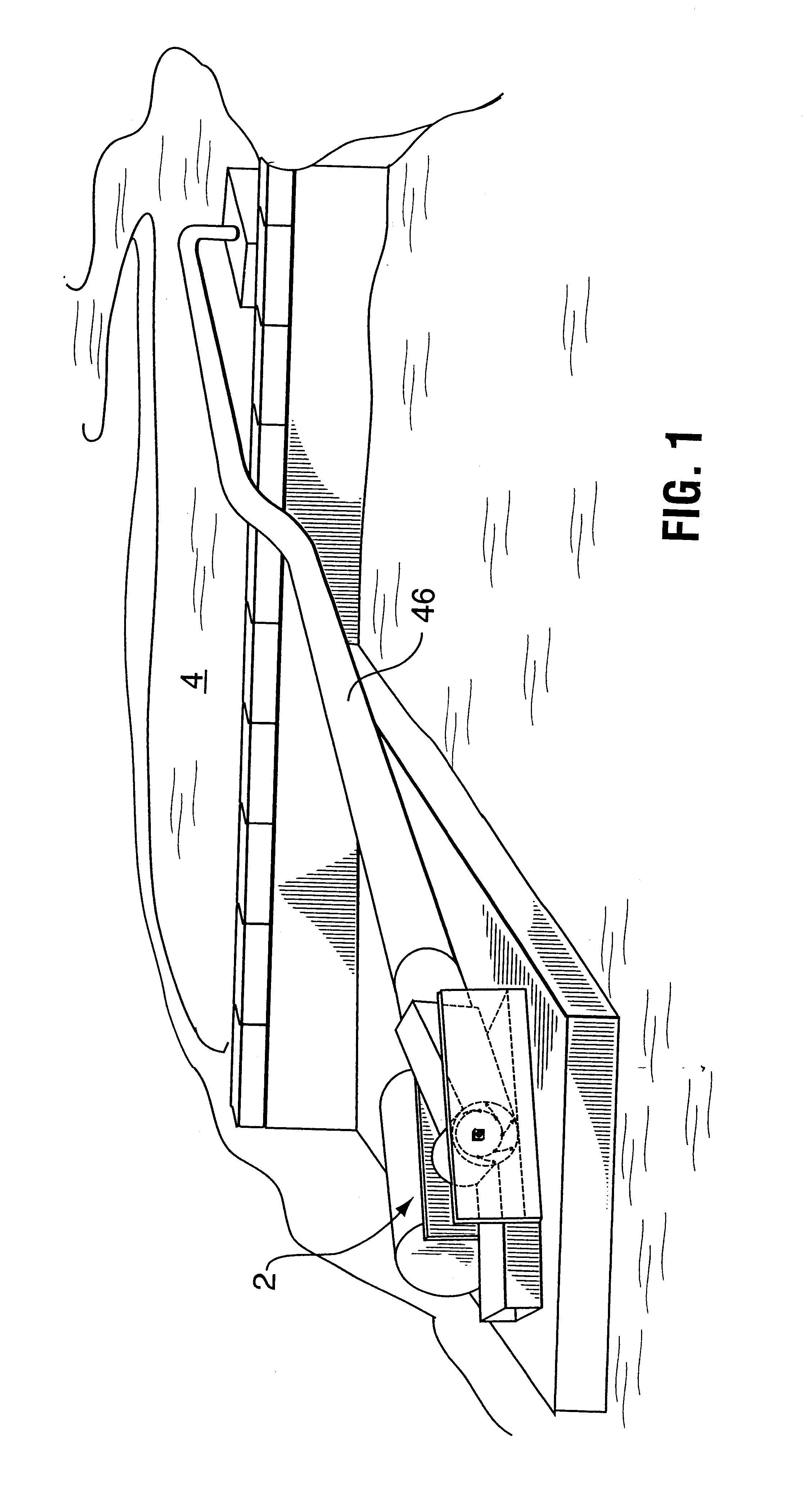
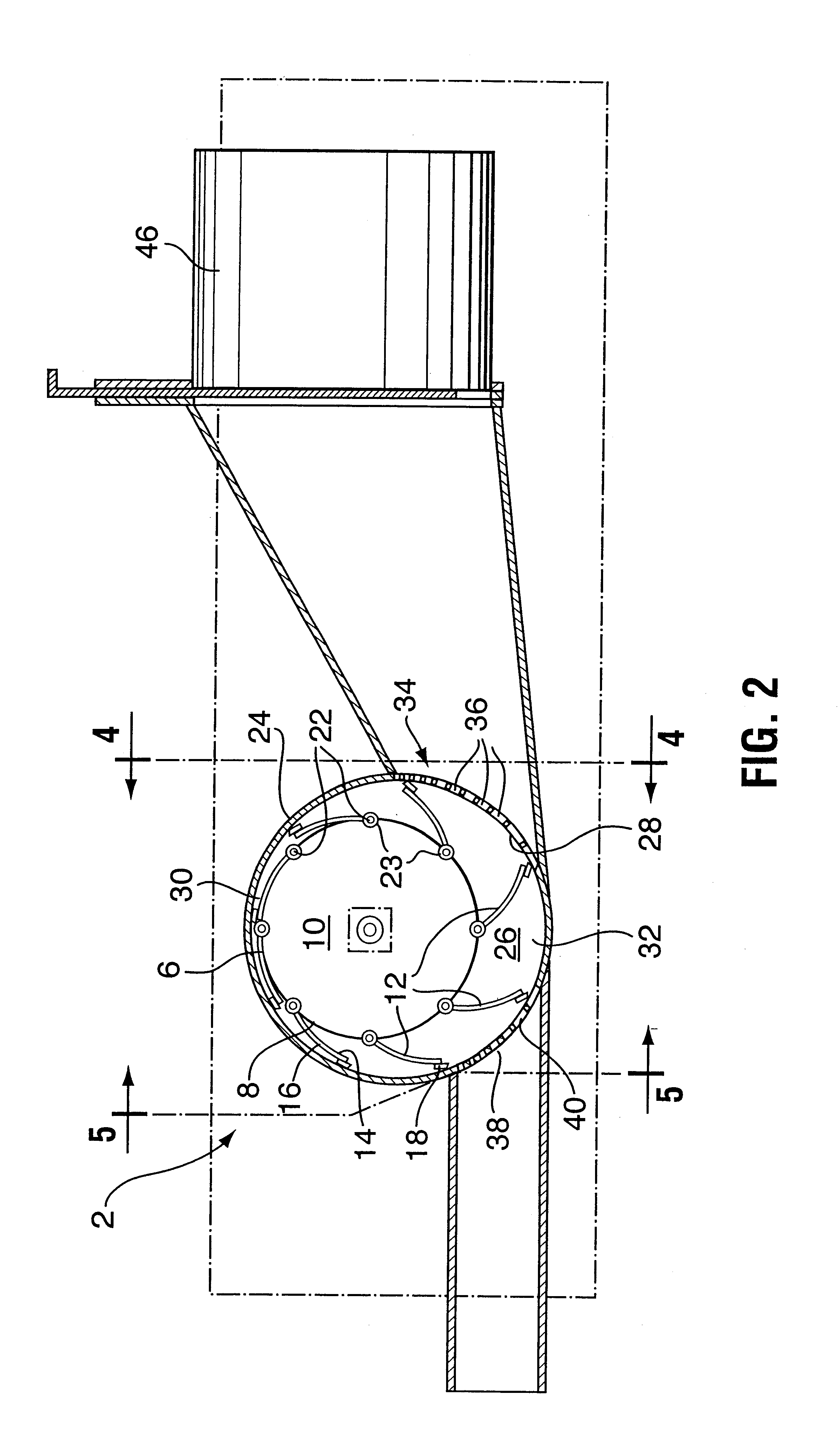
Turning to FIGS. 1 and 2 there is illustrated a low head turbine (2) according to the present invention receiving water input from a stream (4).

Turbine (2) comprises a runner (6) having a cylindrical outer surface (8) extending between opposite ends (10). A plurality of similarly shaped and sized blades (12), having inner sides (14) and outer sides (16) extending between ends (10) are spaced evenly about the surface (8) of runner (6) as illustrated, and extend between the ends (10) of runner (6). Along the outer side (16) are preferably secured strips (18) of a low friction plastic. The inner sides (14) of blades (12) are pivotally secured at pivots (22) to the outer surface (8) of runner (6), in such a manner that the blades can pivot in the direction of rotation of the runner, between a closed position lying adjacent the outer surface (8) of the runner and an open position at ...


PUM


Abstract

A low head water turbine comprising a runner having a cylindrical outer surface and a plurality of similar blades similarly pivotably secured along their inner sides to the outer surface of the runner so as to pivot in the direction of rotation of the runner between a closed position lying adjacent the outer surface of the runner and an open position at an angle thereto. A housing having end walls and a rounded side wall extending therebetween, completely encases the runner and its blades. The runner is eccentrically mounted to end walls of the housing for rotation about a horizontal axis so that the cylindrical outer surface is spaced closer to an upper portion of the housing side wall and farther from a lower portion. A water inlet opening is located in a lower, forward portion of the housing, below the axis of rotation of the runner. A water outlet opening is located in a lower, rearward portion of the housing. During operation of the turbine, the blades will be constricted by the side wall of the housing and thereby moved to the closed position as they approach and pass the upper portion of the housing side wall, and will move to the open position under force of gravity, water and centrifugal force acting on them as they move below the axis of rotation of the runner to the lower position, all the time the housing side wall acting on the outer sides of the blades.

Description

FIELD OF THE INVENTIONThe present invention relates to an improvement in low head water turbines, and more particularly to turbines which can capture energy from heads of water from about six meters, down to about one meter, for use, for example, in generating electricity.BACKGROUND OF THE INVENTIONTraditionally, low head water turbines have been of an open type, as exemplified for example by conventional water wheels, and have had extremely low efficiency. This has meant, for example, that sections of small rivers having a low head or drop, have been unsuitable for generation of hydro electric power. Conventional power generation turbines such as Francis turbines, Kaplan turbines and Peleton turbines traditionally require high heads of water to generate the water pressure and velocity required to move the turbine blades. Such arrangements have necessitated large dams, construction of flumes and the like, necessitating, often, massive capital expenditure.The present invention is int...

Claims


Application Information

Patent Timeline
Patent Type & Authority Patents(United States)
IPC IPC(8): F03B7/00F03B13/08F03B13/00
CPCF03B7/00F03B13/08F03B17/065Y10S415/906Y02E10/223Y02E10/28Y02E10/22Y02E10/20
Inventor GODSALL, TERRENCE GORDONINNES, DONALD ERICINNES, MATTHEW CHRISTOPHER
Owner SALMON RIVER PROJECT LTD THE
Why Eureka
Try Eureka