Fish tank vacuum

Inactive Publication Date: 2005-04-12
MANDIA RALPH
View PDF13 Cites 12 Cited by
  • Summary
  • Abstract
  • Description
  • Claims
  • Application Information

AI Technical Summary

Benefits of technology

It is an object of the invention to produce a system that facilitates cleaning the interior of a fish tank. Accordin

Problems solved by technology

Several practical limitations, however, prevent the true duplication of all environmental constraints.
In addition, as debris accumulates in the fish tank it becomes unsightly.
However, doing so only tends to disperse the debris through the water

Method used


Image

  • Fish tank vacuum
  • Fish tank vacuum
  • Fish tank vacuum

Examples


Embodiment Construction

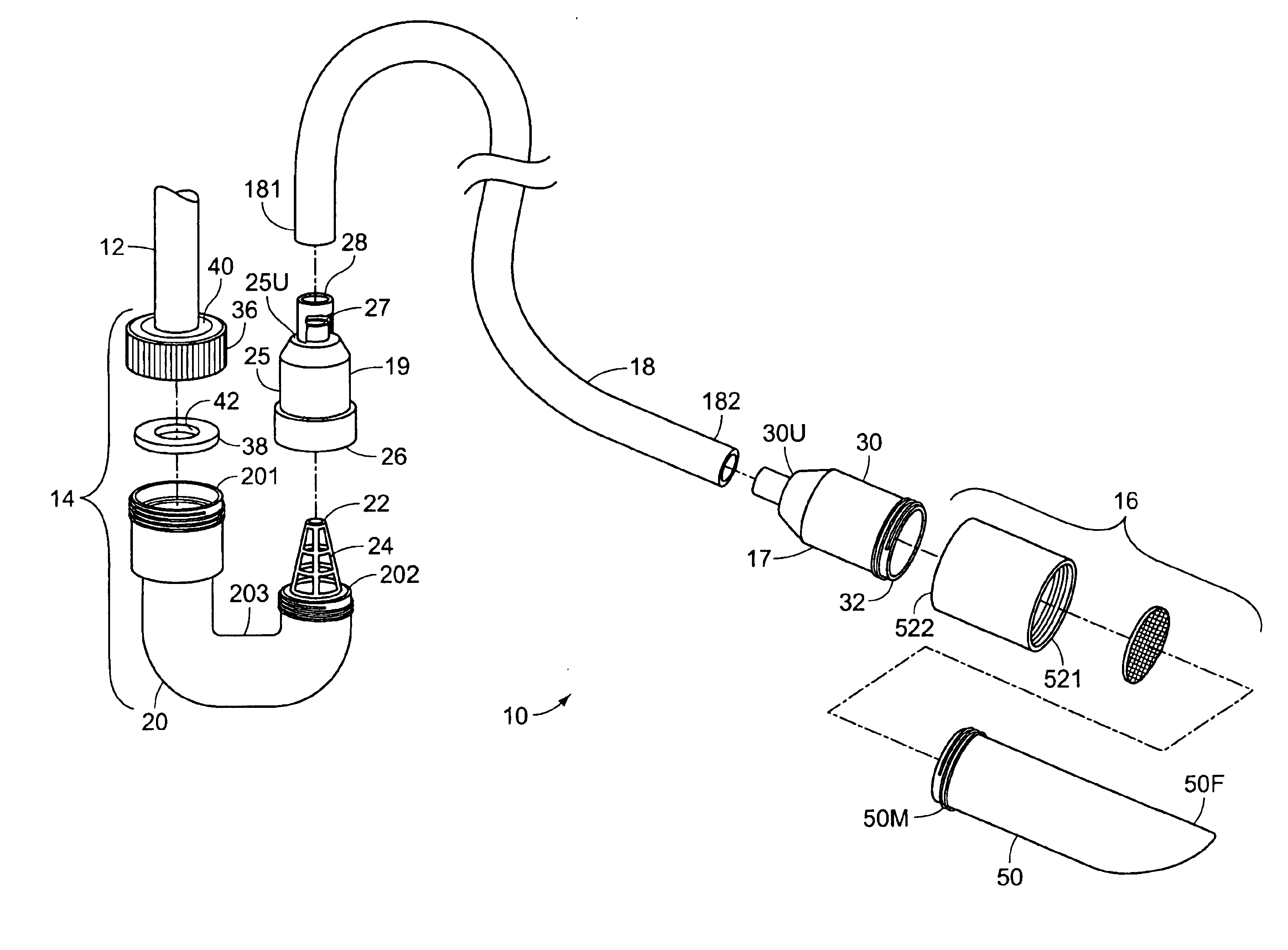
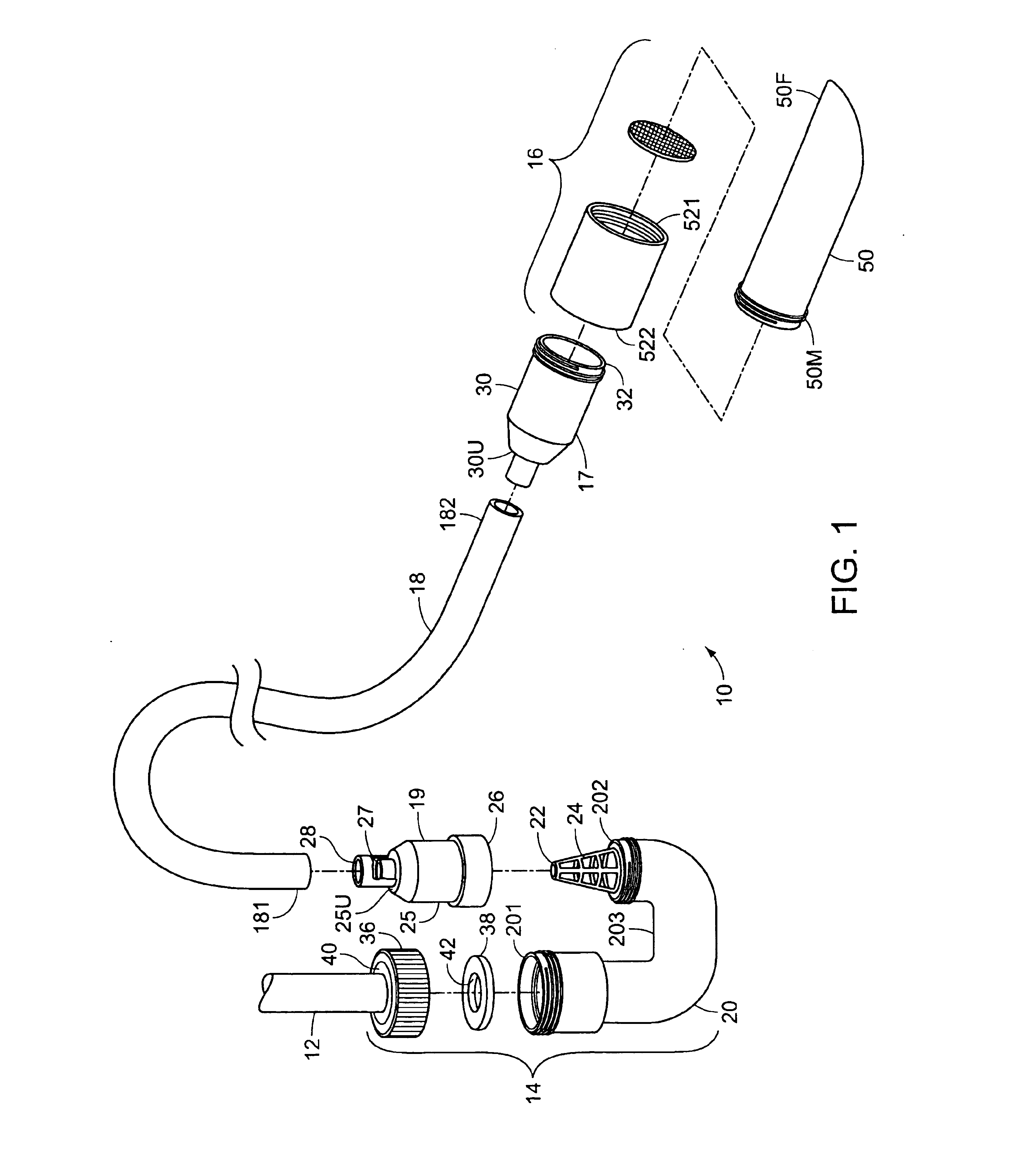
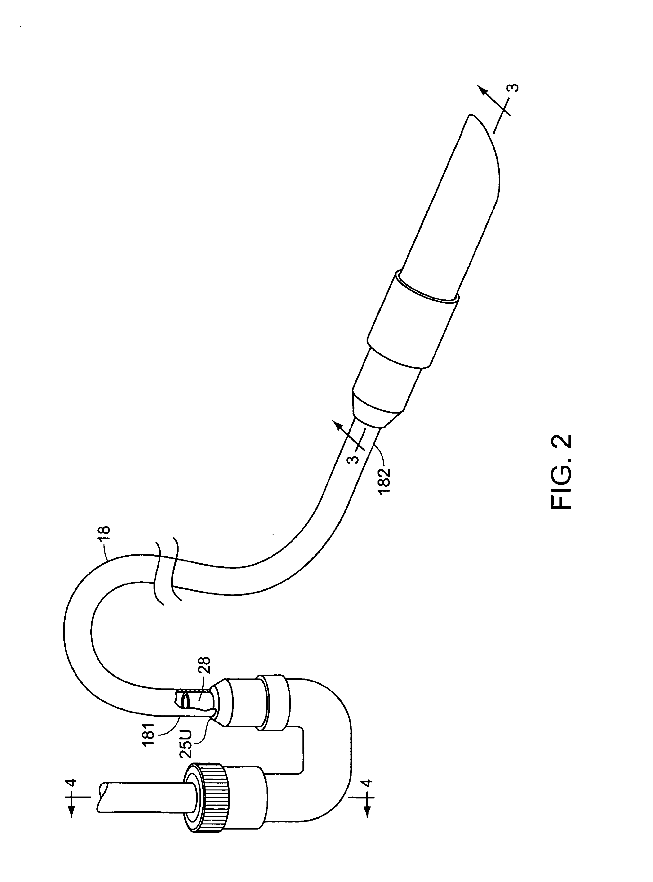
FIG. 1 illustrates a fish tank vacuum 10 for attaching to an existing intake pipe 12. The vacuum 10 has an attachment assembly 14, a nozzle assembly 16, and a flexible hose 18 that connects the attachment assembly 14 and nozzle assembly 16. In particular, the flexible hose 18 is connected to the nozzle assembly 16 with a primary swivel assembly 17, and is connected to the attachment assembly 14 with a secondary swivel assembly 19.

The attachment assembly 14 includes a u-pipe 20 having a first end 201, a second end 202, and a bend 203 therebetween. The first end 201 and second end 202 are both open, externally threaded, and are substantially parallel to each other. The u-pipe 20 is offset such that the second end 202 is closer to the bend 203 than the first end 201. Accordingly, when the first end 201 and second end 202 are oriented upwardly, the second end 202 is lower than the first end 201. A fish screen 22 is removably mounted at the second end 202 extending upwardly from the seco...


PUM

PropertyMeasurementUnit
Flow rateaaaaaaaaaa
Flexibilityaaaaaaaaaa

Abstract

A fish tank vacuum, for use with a fish tank having a fish tank interior and an intake pipe, for removing debris from the fish tank interior with a suction nozzle. An attachment assembly connects to the intake pipe for establishing water flow into the suction nozzle. The suction nozzle is attached to a filter housing that holds a filter disk. Swivel assemblies are connected to the attachment assembly and the filter housing. A flexible tube extends between the swivel assemblies and allows the suction nozzle to easily move around the fish tank interior for debris removal.

Description

BACKGROUND OF THE INVENTIONThe invention relates to a fish tank vacuum. More particularly, the invention relates to a vacuum assembly that attaches to an existing fish tank filtration system inlet pipe and facilitates cleaning debris from the tank interior.A fish tank is a scaled, man-made representation of an actual aquatic habitat. In order to sustain marine life therein, the tank must closely resemble its natural counterpart in everyway. Several practical limitations, however, prevent the true duplication of all environmental constraints. For example, many organisms and microorganisms that keep our oceans, lakes, streams, and rivers clean are typically not present in a fish tank. Accordingly, certain waste debris tends to accumulate, and must be removed before it reaches toxic levels that will-harm the fish. In addition, as debris accumulates in the fish tank it becomes unsightly.One way in which waste levels are controlled in a fish tank is through water changes. Periodically re...

Claims


Application Information

Patent Timeline
IPC IPC(8): A01K61/00A01K63/04
CPCA01K61/003A01K63/045A01K63/04A01K63/10
Inventor MANDIA, RALPH
Owner MANDIA RALPH
Why Eureka
Try Eureka