Method and apparatus for reducing driver count and power consumption in micromechanical flat panel displays

a technology of micromechanical flat panel display and driver count, which is applied in the field of micromechanical optical switch and flat panel display, can solve the problems of limited commercially viable flat panel display screen technology, limited practical applicability, and limited display range of viewing angles, and achieve the effect of reducing the driver count of micromechanical displays

Inactive Publication Date: 2005-04-12
THE GOVERNMENT OF THE US SEC THE AIR FORCE
View PDF8 Cites 51 Cited by
  • Summary
  • Abstract
  • Description
  • Claims
  • Application Information

AI Technical Summary

Benefits of technology

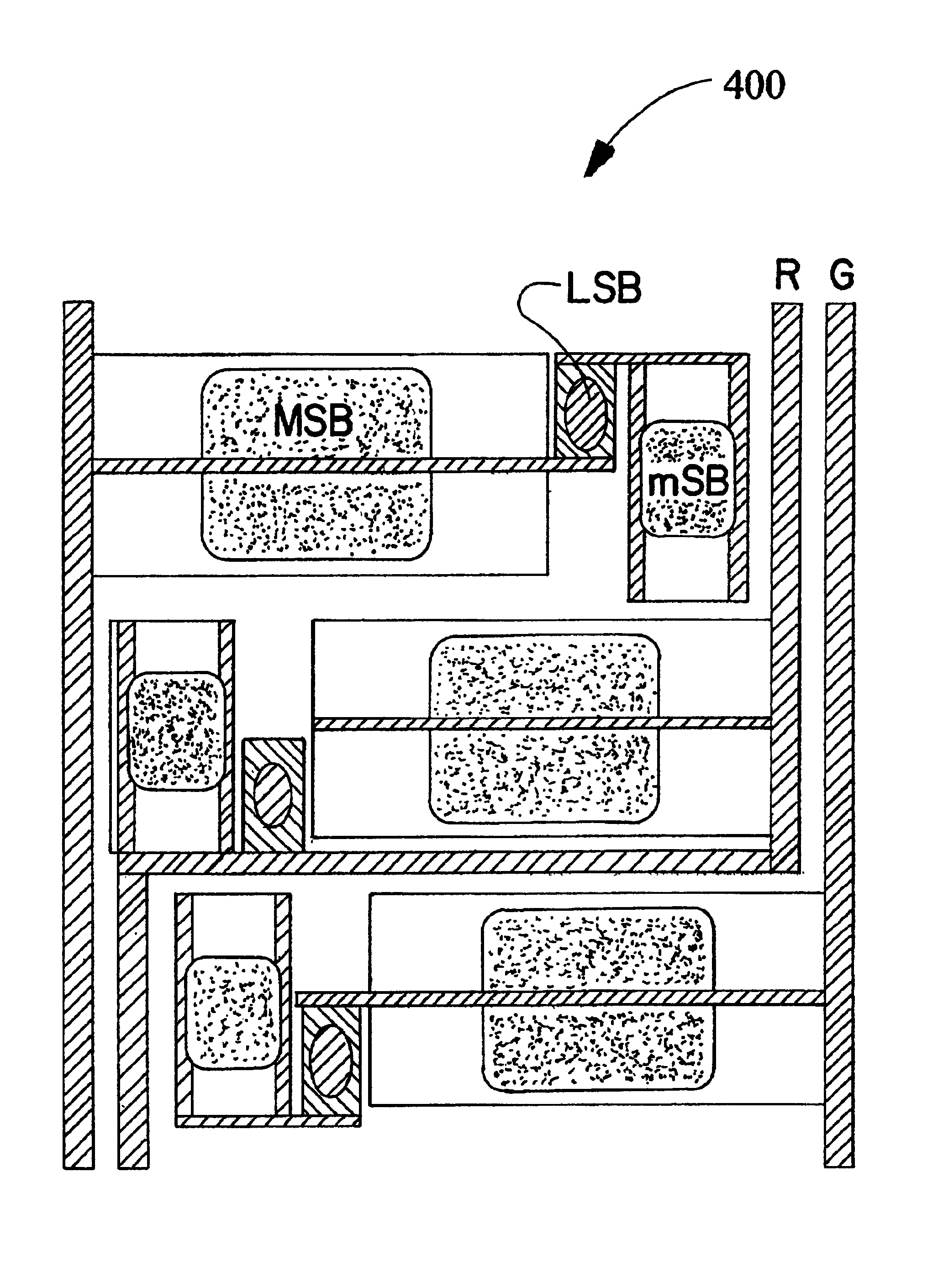
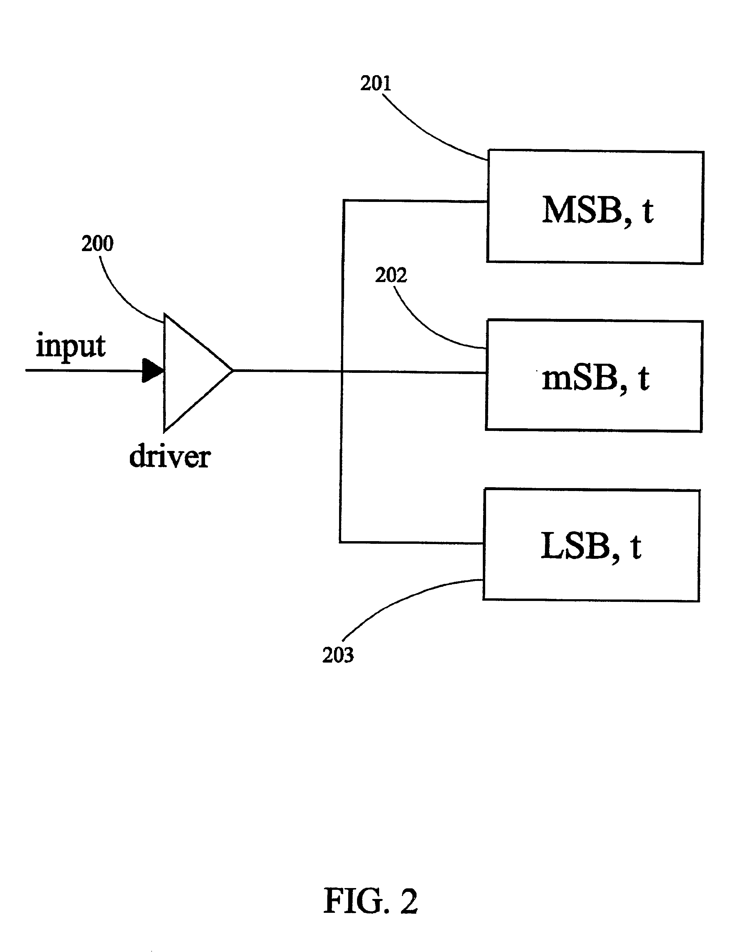
The present invention is a system for reducing driver count in micromechanical displays. It is based on the principle that a single driver can be made to control several elements, provided the cost of drivers and elements remains approximately the same. We can accomplish this by varying both the response time of the elements and the time duration of the signals that control them using three elements.

Problems solved by technology

Yet the many flat panel optical display approaches heretofore proposed and investigated all exhibit serious disadvantages that have limited their practical applicability as a commercially viable flat panel display screen technology.
For example, the class of flat panel displays known as liquid crystal displays require complex manufacturing processes that currently produce relatively low yields, resulting in an overall size limitation for volume production.
In operation, liquid crystal displays require considerable power to maintain a display backlight and these displays provide only a limited range of viewing angles.
Electroluminescent display technology suffers from similar limitations, as well as a limited display color range and limited operational lifecycle.
Active-matrix display technology, which employs an active electronic device at each pixel location of a display, is likewise limited both by high power consumption, production yield constraints, and limited operational lifecycle.
Color gas plasma display technology, like liquid crystal technology, requires a complex manufacturing process to produce an optical display; a gas plasma display relies on complicated packaging schemes for providing reliable containment of a noble gas, resulting in high manufacturing costs.
Even if the cost of a driver circuit is reduced to a few cents, the total cost of the drive circuits alone could exceed $1000 / display, which could make the concept unattractive in commercial markets.
As mentioned in Sterns' previous patent, typical mechanical display schemes have been limited by so many manufacturing complexities and / or operational constraints that they are as yet commercially impractical.
Furthermore, the speed, resolution, and power consumption requirements of the latest optical display applications have heretofore been unachievable by conventional electromechanical display technologies.
But electronic as well as electromechanical display technologies have all required design and performance trade-offs resulting in one or more suboptimal manufacturing or operational considerations.

Method used


Image

  • Method and apparatus for reducing driver count and power consumption in micromechanical flat panel displays
  • Method and apparatus for reducing driver count and power consumption in micromechanical flat panel displays
  • Method and apparatus for reducing driver count and power consumption in micromechanical flat panel displays

Examples


Embodiment Construction

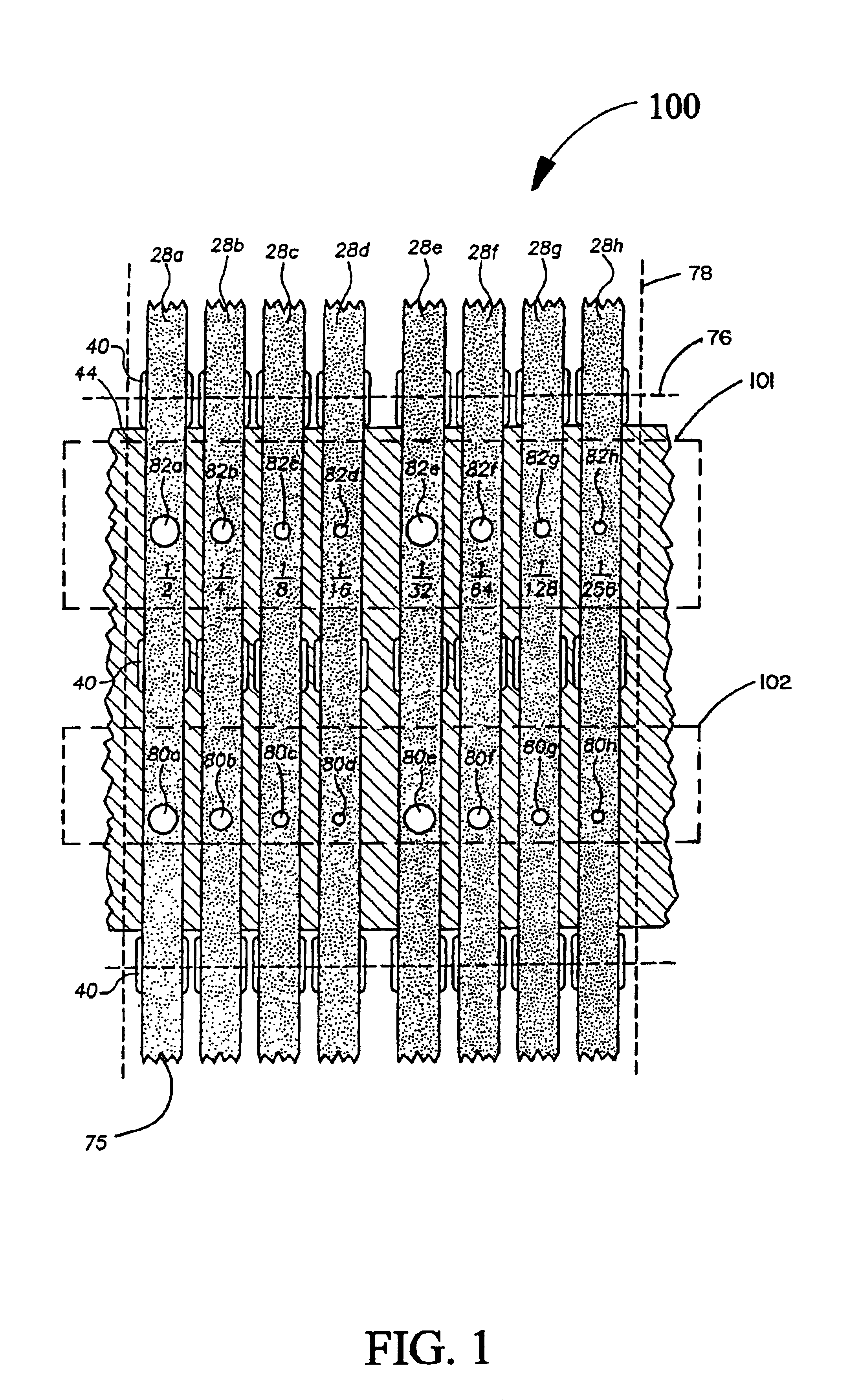
The present invention is a system for reducing the driver count in micromechanical panel displays, and is a direct improvement with application to U.S. Pat. No. 5,771,321 issued Jun. 23, 1998 entitled, “Micromechanical optical switch and flat panel display” invented by Stern. The prior Stern patent is discussed to show the applicability of this improvement as follows.

The system of the Stern patent is shown in FIG. 1. It provides an optical coupling switch and optical display employing an array of optical coupling switches that overcome limitations of past optical switches and displays to achieve superior display switch speed, display efficiency, compact geometry, and ease of manufacture. The optical coupling switch of the invention and the Stern patent, includes a light storage plate that is adapted to set up conditions for total internal reflection such that light injected into the plate is internally reflected. A light tap is disposed proximal to a coupling surface of a light stor...


PUM


Abstract

A micromechanical panel display driver is shown in which only one driver and control bus are needed for each color. Furthermore, the elements are made with uniform film thicknesses, thereby minimizing the number of steps needed to fabricate the display. Here 6 bits are provided with temporal and aperture weighting. The use of temporal weighting generally requires the activation of most pixels twice/frame, which consumes considerable power. It should also be possible to eliminate temporal weighting by redistributing the contact area into a larger number of aperture weights and by adding a row electrode. Here pixels are activated only in response to a charge in the image. This generally reduces the drive power, since many pixels in a typical image do not change from frame to frame.

Description

BACKGROUND OF THE INVENTIONThe present invention relates generally to panel display systems and more specifically to an improvement in the invention of U.S. Pat. No. 5,771,321, issued Jun. 23, 1998 entitled “Micromechanical optical switch and flat panel display” by Stern, the disclosure of which is specifically incorporated herein by reference.As mentioned in the above-cited patent, electronically controlled optical displays, and particularly flat panel optical displays, which generally are distinguished by their relative slimness and ability to produce a direct, as opposed to a projected, display image are of increasing technological importance for a wide range of applications. Flat panel optical displays that produce directly viewable video images such as text and graphics are, in theory, ideally suited as television monitors, computer monitors, and other such display screen scenarios. Yet the many flat panel optical display approaches heretofore proposed and investigated all exhi...

Claims


Application Information

Patent Timeline
Patent Type & Authority Patents(United States)
IPC IPC(8): G09G3/34G09G3/20
CPCG09G3/3473G09G3/207G09G3/2077
Inventor STERN, ERNEST
Owner THE GOVERNMENT OF THE US SEC THE AIR FORCE
Why Eureka
Try Eureka