Single tone process window metrology target and method for lithographic processing

a single-tone process and metrology target technology, applied in the direction of microlithography exposure apparatus, instruments, measurement devices, etc., can solve the problems of not being able to determine the effect of focus, not being able to print dual-tone targets, and not being able to provide electrically testable monitors

Inactive Publication Date: 2005-04-12
INT BUSINESS MASCH CORP
View PDF26 Cites 32 Cited by
  • Summary
  • Abstract
  • Description
  • Claims
  • Application Information

AI Technical Summary

Problems solved by technology

A drawback of these methods is that some product levels either do not allow the printing of dual-tone targets due to ground rule violations, or require exposure in a regime where the dual-tone targets do not provide adequate response.
Because the Starikov structure is only sensitive to dose, it is not able to determine the effects of focus.
In addition to the aforementioned problems in visual monitoring, the prior art also does not provide for electrically testable monitors to separate the effects of dose and focus.

Method used


Image

  • Single tone process window metrology target and method for lithographic processing
  • Single tone process window metrology target and method for lithographic processing
  • Single tone process window metrology target and method for lithographic processing

Examples


Embodiment Construction

)

In describing the preferred embodiment of the present invention, reference will be made herein to FIGS. 1-8 of the drawings in which like numerals refer to like features of the invention. Features of the invention are not necessarily shown to scale in the drawings.

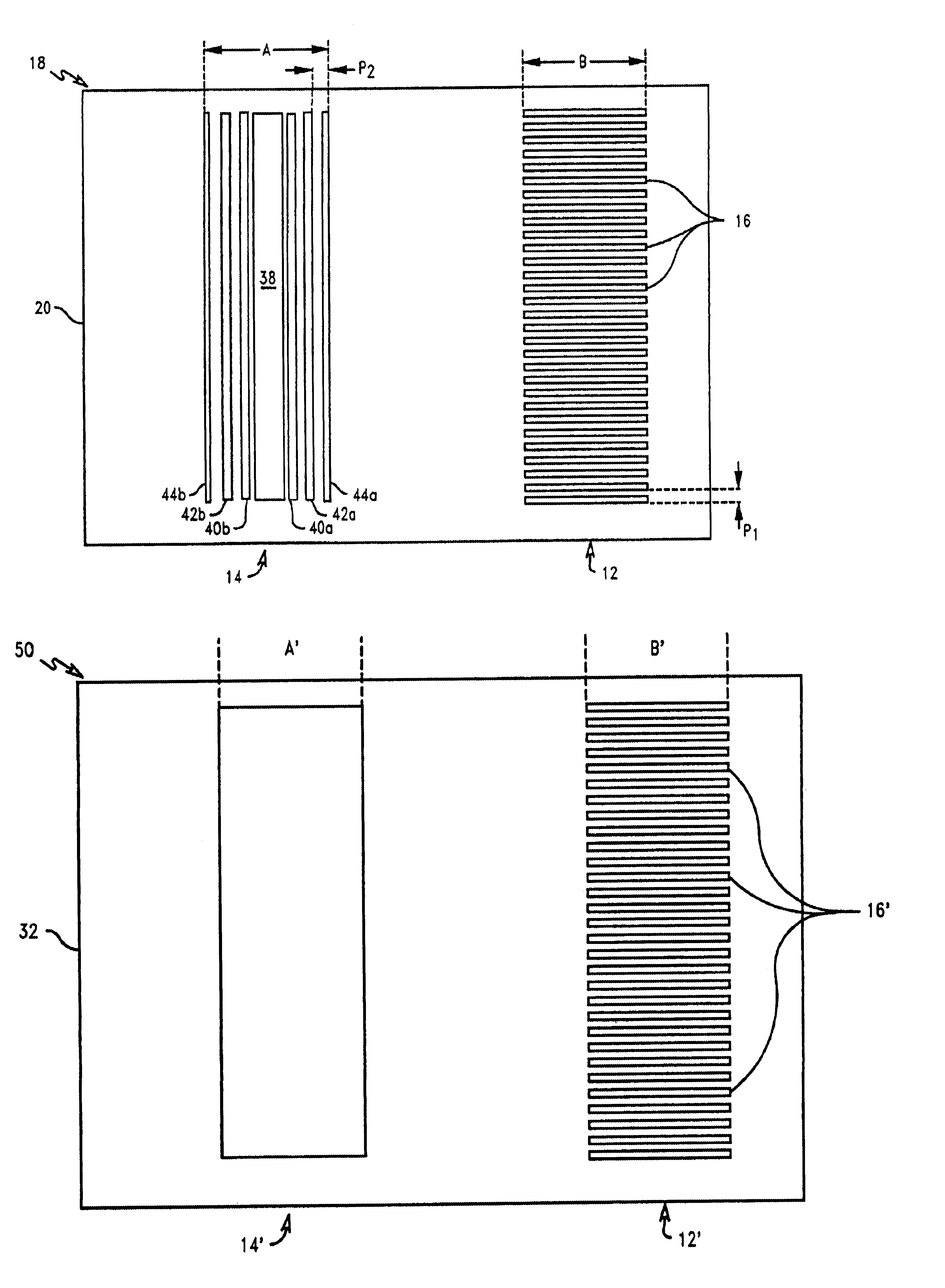
The concept of image shortening in photolithographic targets is disclosed in U.S. Pat. Nos. 5,712,707 and 5,976,740, the disclosures of which are hereby incorporated by reference. The concept of image shortening is incorporated in the present invention which provides both an image shortening visual test pattern or target, for low resolution metrology targets, and an electrically testable image shortening monitor, for high resolution metrology targets. As disclosed in U.S. Pat. No. 5,976,740 the simultaneous tracking of line and space length enables the unique solution of relative dose and focus measurements. By measuring the resistance of structures affected by this image shortening phenomena, it is possible to calibrate ...


PUM

PropertyMeasurementUnit
widthaaaaaaaaaa
widthaaaaaaaaaa
lengthaaaaaaaaaa

Abstract

A metrology target mask includes a first array of spaced, substantially parallel elements having essentially the same length and width. Ends of the individual elements are aligned to form opposing array edges. The target mask also includes a second array of elements comprising a central element having a length and a width, and a plurality of spaced, substantially parallel outer elements having a length and a width. The width of the outer elements is less than the width of the central element, with edges of outer elements on each side of and farthest from the central element forming opposing array edges. The pitch of the outer elements is selected such that the outer elements are not resolvable after lithographic printing. After printing, the first array is sensitive to both dose and focus, and the second array is sensitive to dose but not focus, of the energy beam.

Description

BACKGROUND OF THE INVENTION1. Field of the InventionThe present invention relates generally to manufacturing processes requiring lithography and, more particularly, to monitoring of lithographic and etch process conditions used in microelectronics manufacturing which is particularly useful for monitoring pattern features with dimensions on the order of less than 0.5 micron.2. Description of Related ArtControl of a lithographic imaging process requires the optimization of exposure and focus conditions in lithographic processing of product substrates or wafers. Likewise, it is also important to optimize etching and other parameters on product wafers. Generally, because of the variations in exposure and focus, patterns developed by lithographic processes must be continually monitored or measured to determine if the dimensions of the patterns are within acceptable range. The importance of such monitoring increases considerably as the resolution limit, which is usually defined as minimum...

Claims


Application Information

Patent Timeline
Patent Type & Authority Patents(United States)
IPC IPC(8): G03F7/20
CPCG03F7/70641G03F7/70558
Inventor AUSSCHNITT, CHRISTOPHER P.BRUNNER, TIMOTHY A.
Owner INT BUSINESS MASCH CORP
Why Eureka
Try Eureka