Apparatus and methods for detecting overlay errors using scatterometry

a scatterometry and apparatus technology, applied in the field of overlay determination, can solve the problems of detailed knowledge of the film stack, increasing inefficiencies and costs, and reducing throughput, and achieve the effect of improving the accuracy of the detection method and reducing the cost of the detection method

Active Publication Date: 2007-07-10
KLA TENCOR TECH CORP
View PDF122 Cites 114 Cited by
  • Summary
  • Abstract
  • Description
  • Claims
  • Application Information

AI Technical Summary

Problems solved by technology

A large number of parameters could require increased processing resources, may introduce corresponding errors, and may delay the results, thereby possibly decreasing throughput and increasing inefficiencies and costs.
Another disadvantage of certain existing approaches to determination of overlay based on scatterometry is the detailed knowledge of the film stack, film materials, and pattern element profiles that may be required to determine accurate theoretical spectra to compare to the measured spectra.
Yet another disadvantage of certain existing approaches to determination of overlay based on scatterometry is the accurate knowledge of the scatterometry optical system that may be required to determine accurate theoretical spectra to compare to the measured spectra.

Method used


Image

  • Apparatus and methods for detecting overlay errors using scatterometry
  • Apparatus and methods for detecting overlay errors using scatterometry
  • Apparatus and methods for detecting overlay errors using scatterometry

Examples


fifth embodiment

[0125]FIG. 5(f) is a diagrammatic representation of a fixed, discrete channel optical system in accordance with the present invention. In this embodiment, the system includes a mirror having spectroscopic apertures 562. That is, the mirror is reflected, except for a plurality of apertures which let the light from the sample pass through in particular spatial portions. FIG. 5(g) is a diagrammatic representation of the aperture mirror of FIG. 5(f) in accordance with one embodiment of the present invention. As shown, the mirror 572 includes four etched apertures 574. The apertures 574 are etched within a mirror reflective substrate 572. In one implementation, the light which corresponds to each center portion of each target pass through the mirror to separate detectors, e.g., fiber pickoffs to spectrometers 564. The remaining portion of the target image, excluding the central image portions for each target, is reflected by mirror 562 to a camera. FIG. 5(h) is a top view representation ...

first embodiment

[0253]Any suitable tool or combination of tools may be used to perform both imaging and scatterometry overlay. FIG. 11d illustrates a combinational imaging and scatterometry system 1160 in accordance with the present invention. In this implementation, the imaging optical assembly 1162 is separate from the scatterometry optical assembly 1164. In other words, the imaging assembly 1162 is spatially separate from the scatterometry assembly 1164 and both assemblies are stand alone components. In this implementation, the assemblies 1162 and 1164 do not share any optical components, but are designed to compliment and collaborate with each other. For instance, overlay data may be passed between the two devices for implementation of one or more of the above described techniques on either assembly or on a separate processor (not shown).

[0254]The combination system 1160 also includes a stage 1166 for holding the sample thereon. The stage and the optical assemblies move in relation to one anoth...

second embodiment

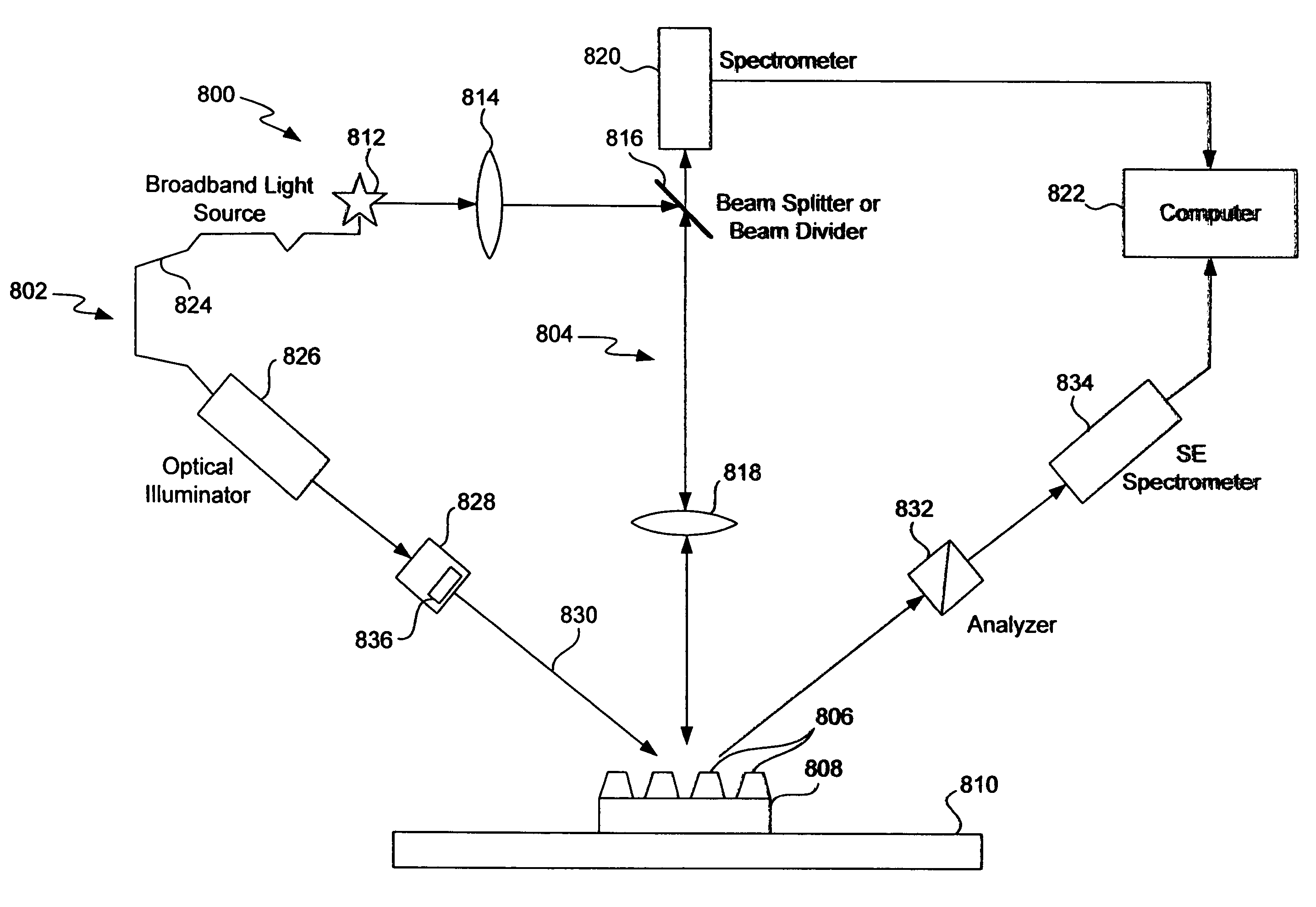
[0256]FIG. 11e illustrates a combinational imaging and scatterometry system 1170 in accordance with the present invention. In this implementation, the imaging and scatterometry optical assemblies are integrated together. The imaging and scatterometry optical assemblies may share one or more components. For example, the imaging and scatterometry assemblies may share a same light source. As shown, the combination system 1170 includes an imaging microscope 1172 configured for imaging overlay determination and light source 1174 for directing any form of optical beam towards a sample on stage 1178 and detector 1176 for measuring a resulting signal in response to the incident optical beam. For example, the imaging and scatterometry assemblies may share a same light source. The imaging and scatterometry assemblies may also be configured to share data, which may be analyzed in either assembly or by an independent processor (not shown).


PUM

PropertyMeasurementUnit
angleaaaaaaaaaa
wavelengthsaaaaaaaaaa

Abstract

Disclosed is a method for determining an overlay error between at least two layers in a multiple layer sample. A sample having a plurality of periodic targets that each have a first structure in a first layer and a second structure in a second layer is provided. There are predefined offsets between the first and second structures. Using a scatterometry overlay metrology, scatterometry overlay data is obtained from a first set of the periodic targets based on one or more measured optical signals from the first target set on the sample. Using an imaging overlay metrology, imaging overlay data is obtained from a second set of the periodic targets based on one or more image(s) from the second target set on the sample.

Description

CROSS REFERENCE TO RELATED PATENT APPLICATION[0001]This application claims priority of the following now abandoned U.S. Provisional Patent Applications: (1) Application No. 60 / 504,093, entitled APPARATUS AND METHODS FOR DETECTING OVERLAY ERRORS USING SCATTEROMETRY, by Walter D. Mieher, filed 19 Sep. 2003, (2) Application No. 60 / 449,496, entitled METHOD AND SYSTEM FOR DETERMINING OVERLAY ERRORS BASED ON SCATTEROMETRY SIGNALS ACQUIRED FROM MULTIPLE OVERLAY MEASUREMENT PATTERNS, by Walter D. Mieher, filed 22 Feb. 2003, and (3) Application No. 60 / 498,524, filed 27 Aug. 2003, entitled “METHOD AND APPARATUS COMBINING IMAGING AND SCATTEROMETRY FOR OVERLAY METROLOGY”, by Mike Adel.[0002]This application is also a continuation-in-part of U.S. application Ser. No. 10 / 729,838, by Walter D. Mieher et al. filed 5 Dec. 2003. These applications are herein incorporated by reference in their entirety.BACKGROUND OF THE INVENTION[0003]The present invention relates to determination of overlay between s...

Claims


Application Information

Patent Timeline
Patent Type & Authority Patents(United States)
IPC IPC(8): G01B11/00G03F7/20G03F9/00
CPCG01N21/956G03F7/70625G03F7/70633G03F9/7049G03F9/7084G03F9/7088G03F7/70683G01N2021/213
Inventor MIEHER, WALTER D.LEVY, ADYGOLOVANESKY, BORISFRIEDMANN, MICHAELSMITH, IANADEL, MICHAEL E.GHINOVKER, MARKBEVIS, CHRISTOPHER F.KNOLL, NOAMBARUCH, MOSHE
Owner KLA TENCOR TECH CORP
Why Eureka
Try Eureka