
System and method for boundary estimation using CT metrology

a technology of ct metrology and system and method, applied in the field of non-invasive imaging, can solve the problems of ct based techniques having a relatively low inspection accuracy, unable to measure internal features, and deterring widespread use,

Inactive Publication Date: 2007-04-10
GENERAL ELECTRIC CO
View PDF9 Cites 119 Cited by
  • Summary
  • Abstract
  • Description
  • Claims
  • Application Information

AI Technical Summary

Benefits of technology

This approach enhances inspection accuracy by reducing artifacts and computational time, allowing for precise capture of both internal and external features of objects, while being computationally efficient and cost-effective.

Problems solved by technology

Modalities such as CMM and laser-based profilometry typically measure external surfaces with high accuracy, but cannot measure internal features unless the object is cut open.
However, CT based techniques may also have a relatively low inspection accuracy, which may deter their widespread use.
For example, in the area of reverse engineering, CT may be unsatisfactory for capturing detailed external surface features, which may be crucial for capturing the design intent.
However, because FBP is based on an oversimplification of the CT data acquisition into an ideal mathematical transform such as parallel beam Radon transform, Fan Beam transform, cone beam transform or other geometric line integral transform depending on the particular acquisition geometry, the reconstructed image may suffer from artifacts such as beam hardening and partial volume as discussed above, contributing to degraded image quality and inspection accuracy.
However, iterative reconstruction approaches may be computationally inefficient, typically having long computation times due to their intensive computational requirements.
Furthermore, both FBP techniques and iterative reconstruction techniques may have limited accuracy due to their reliance on pixel grid representations and / or image segmentation.

Method used


Image

  • System and method for boundary estimation using CT metrology
  • System and method for boundary estimation using CT metrology
  • System and method for boundary estimation using CT metrology

Examples


Embodiment Construction

[0014]The present techniques are generally directed to computed tomography (CT) reconstruction method resulting in improved inspection accuracy. Such reconstruction techniques may be useful in a variety of imaging contexts, such as CT imaging and inspection systems, CT metrology or others. Though the present discussion provides examples in a industrial imaging context, one of ordinary skill in the art will readily apprehend that the application of these techniques in other contexts, such as for medical imaging, security screening, and / or baggage or package inspection, is well within the scope of the present techniques.

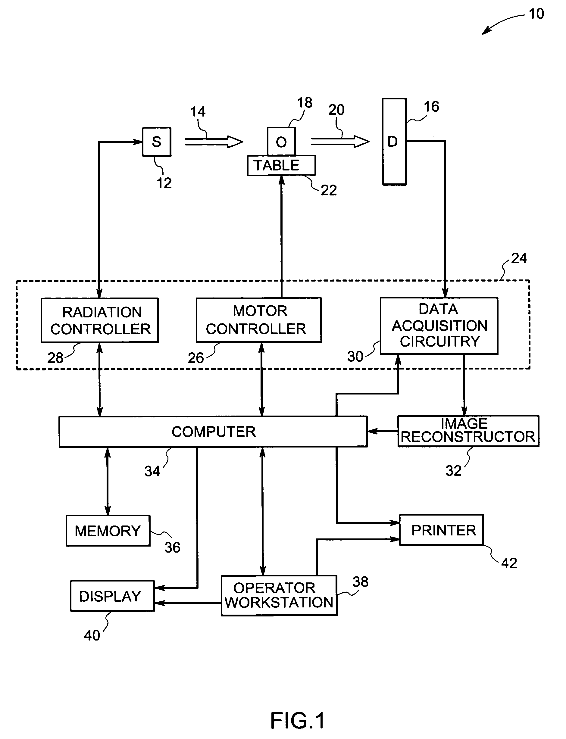
[0015]Referring now to FIG. 1, an imaging system 10 for use in accordance with the present technique is illustrated. In the illustrated embodiment, the imaging system 10 is a computed tomography (CT) system designed both to acquire original image data and to process the image data for display and analysis in accordance with the present technique. In the illustrated emb...


PUM

PropertyMeasurementUnit
computed tomographyaaaaaaaaaa
CTaaaaaaaaaa
distanceaaaaaaaaaa

Abstract

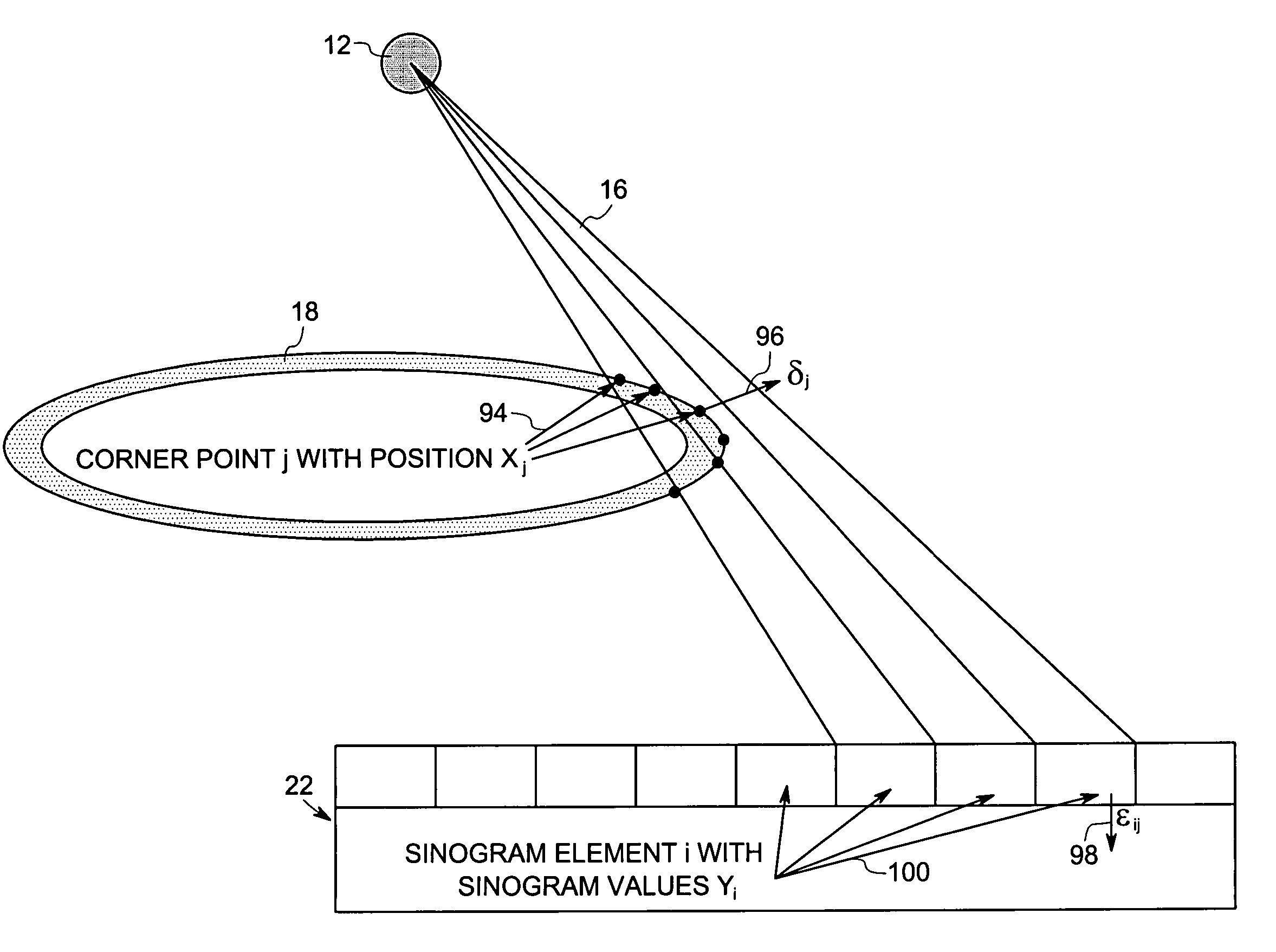
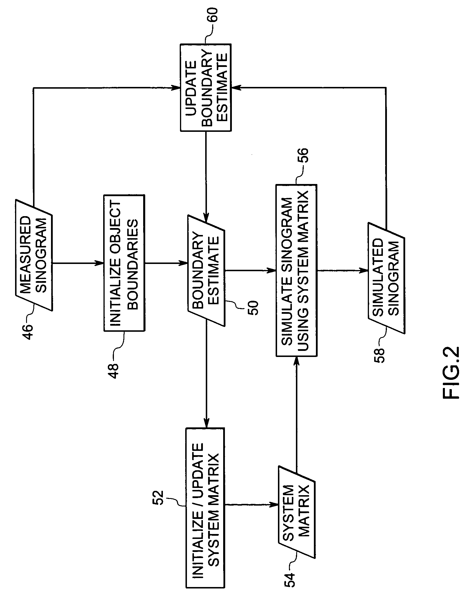
A technique is provided for CT reconstruction for use in CT metrology. The boundary based CT reconstruction method includes the steps of initializing a boundary of an object to obtain a boundary estimate, defining a forward model based on the boundary estimate, linearizing the forward model to obtain a system matrix and implementing an iterative image reconstruction process using the system matrix to update the boundary estimate.

Description

BACKGROUND[0001]The present invention relates generally to the field of non-invasive imaging and more specifically to the field of computed tomography (CT) imaging and inspection systems. In particular, the present invention relates to boundary-based CT reconstruction techniques for use in CT metrology.[0002]Various types of measurement systems such as computed tomography (CT), coordinate measuring machines (CMM), laser-based profilometry, light gauge, infrared and others are used in industrial inspection processes for a wide variety of applications, such as for measuring wall thickness or for identifying defects in manufactured parts. Each measurement / inspection system has advantages and disadvantages. Modalities such as CMM and laser-based profilometry typically measure external surfaces with high accuracy, but cannot measure internal features unless the object is cut open. To date, CT is the most versatile of the measurement / inspection systems for revealing both the internal and ...

Claims


Application Information

Patent Timeline
Patent Type & Authority Patents(United States)
IPC IPC(8): G01N23/00G06T11/00
CPCG06T11/006G06T2211/424
Inventor DE MAN, BRUNO KRISTIAAN BERNARDBASU, SAMIT KUMARYE, JONG CHUL
Owner GENERAL ELECTRIC CO
Learn More