Metrology Methods, Metrology Apparatus and Device Manufacturing Method

a technology of metrology and manufacturing methods, applied in the direction of photomechanical equipment, instruments, x-ray tubes, etc., can solve the problems of not being able to meet the typical dimensions of real product features, the method is made with optical wavelengths, and the performance specifications become ever tighter. , to achieve the effect of a higher angle of incidence and more accurate modeling of the periodic structur

Active Publication Date: 2017-06-29
ASML NETHERLANDS BV
View PDF1 Cites 118 Cited by
  • Summary
  • Abstract
  • Description
  • Claims
  • Application Information

AI Technical Summary

Benefits of technology

[0020]The inventors have recognized that radiation in the extreme ultraviolet (EUV) waveband offers particular advantages for metrology of CD, overlay and other properties of small metrology targets. Conveniently these small metrology targets may again have the form of periodic structures. Compared with the optical scatterometry commonly practiced, EUV rays will not be strongly influenced by underlying features, and modeling of the periodic structure itself can be more accurate as a result. Compared with X-rays, there is potential to focus the EUV radiation to a finer spot without undue loss of power. Compared with X-rays, there is potential to use a much higher angle of incidence. By providing in addition a suitable EUV optical system for illumination and detection of the target, EUV radiation can be formed into a small enough spot for in-die metrology, even when the spot is elongated by the grazing incidence. In order to obtain sufficient information for CD metrology, spectral properties across a range of EUV wavelengths can be measured.

Problems solved by technology

As technology develops, however, performance specifications become ever tighter.
Moreover, small target techniques have not been developed for measurement of other parameters such as line width or critical dimension (CD).
A further limitation of current methods is that they are made with optical wavelengths, much greater than the typical dimensions of real product features.
CD metrology suffers from low accuracy, cross-talk between parameters of interest and also between parameters of interest and other hidden parameters (process robustness).
As the microscopic structures shrink and become more and more complex in geometry (going to 3-D structures, for example), known techniques of CD metrology struggle to provide accuracy, precision, and speed.
T-SAXS signals tend to be very weak, especially when the target size is small.
Therefore the measurements tend to be too time-consuming for use in high-volume manufacturing.
Unfortunately, the small target size requires a small spot size and consequently even longer measurement times.
However, such measurements are different from the measurement of CD in a periodic structure.
Moreover, particularly in view of the very shallow grazing incidence angles involved, none of these known techniques is suitable for metrology on small targets such as an in-die grating.

Method used


Image

  • Metrology Methods, Metrology Apparatus and Device Manufacturing Method
  • Metrology Methods, Metrology Apparatus and Device Manufacturing Method
  • Metrology Methods, Metrology Apparatus and Device Manufacturing Method

Examples


application examples

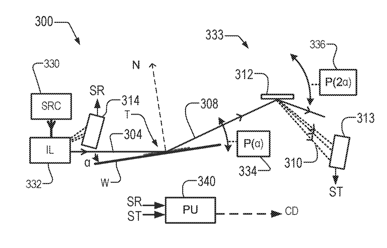
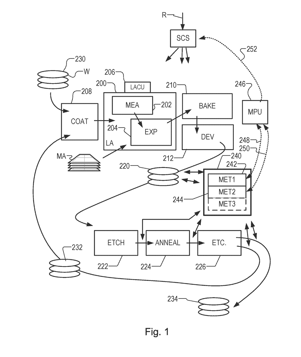
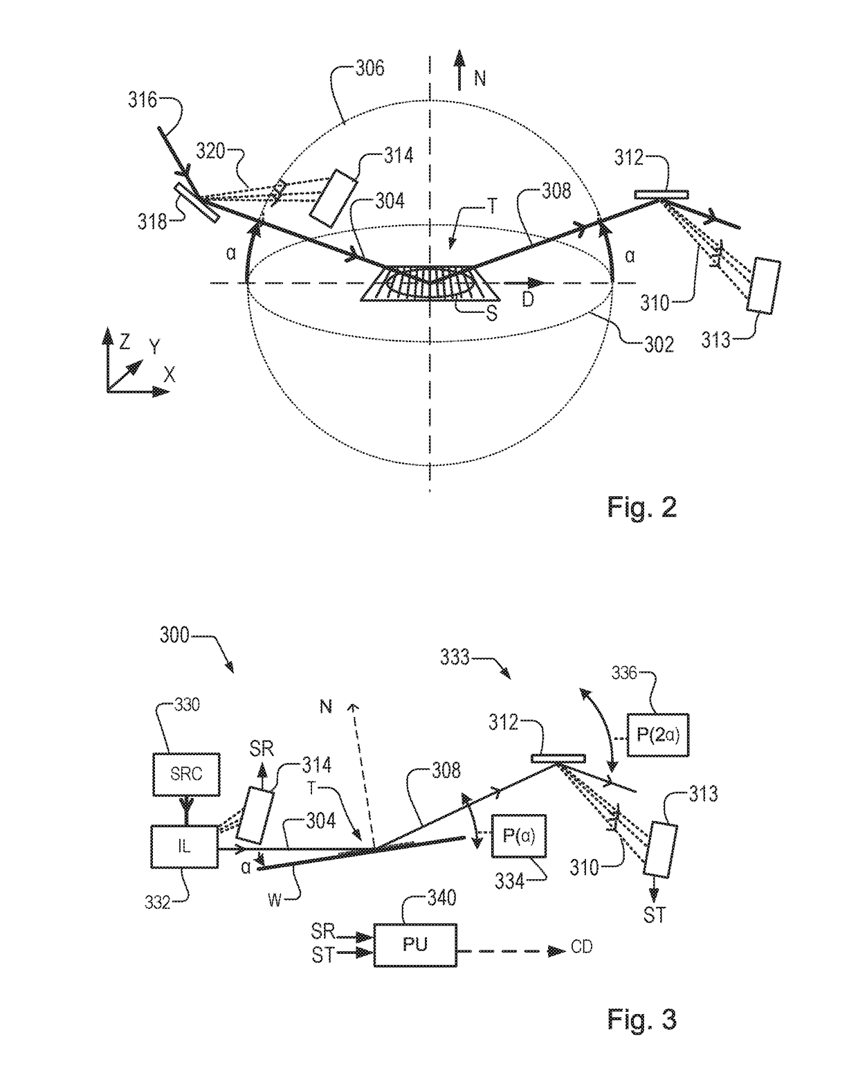
[0132]FIG. 12 shows a generic example of a hybrid metrology system in which first, second and optionally third metrology apparatuses are provided. Each metrology apparatus comprises a source SRC1 / 2 / 3, an illumination system IL1 / 2 / 3 and a detection system DET1 / 2 / 3. A hybrid metrology apparatus can be produced which includes both EUV metrology apparatus 244 for performing and longer-wavelength optical metrology apparatus 240 for performing more conventional scatterometry measurements. Both apparatuses may work simultaneously on the same parts or different parts of a same substrate W. The two apparatuses may in practice operate at different times, while sharing common components such as substrate handling and positioning systems. The metrology apparatuses may be integrated with either the lithographic apparatus LA itself or within the lithographic cell LC. Within the metrology processing unit MPU, dedicated modules 1210-1 / 2 / 3 are provided to process to some extent spectrum data receive...


PUM

PropertyMeasurementUnit
wavelengthsaaaaaaaaaa
grazing angle of incidenceaaaaaaaaaa

Abstract

Hybrid metrology apparatus (1000, 1100, 1200, 1300, 1400) measures a structure (T) manufactured by lithography. An EUV metrology apparatus (244, IL1/DET1) irradiates the structure with EUV radiation and detects a first spectrum from the structure. Another metrology apparatus (240, IL2/DET2) irradiates the structure with second radiation comprising EUV radiation or longer-wavelength radiation and detects a second spectrum. Using the detected first spectrum and the detected second spectrum together, a processor (MPU) determines a property (CD/OV) of the structure. The spectra can be combined in various ways. For example, the first detected spectrum can be used to control one or more parameters of illumination and/or detection used to capture the second spectrum, or vice versa. The first spectrum can be used to distinguish properties of different layers (T1, T2) in the structure. First and second radiation sources (SRC1, SRC2) may share a common drive laser (LAS).

Description

BACKGROUND[0001]Field of the Invention[0002]The present invention relates to methods and apparatus for metrology usable, for example, in the manufacture of devices by lithographic techniques and to methods of manufacturing devices using lithographic techniques. Methods of measuring critical dimension (line width) are described, as a particular application of such metrology. Methods of measuring asymmetry-related parameters such as overlay are also described.[0003]Background Art[0004]A lithographic apparatus is a machine that applies a desired pattern onto a substrate, usually onto a target portion of the substrate. A lithographic apparatus can be used, for example, in the manufacture of integrated circuits (ICs). In that instance, a patterning device, which is alternatively referred to as a mask or a reticle, may be used to generate a circuit pattern to be formed on an individual layer of the IC. This pattern can be transferred onto a target portion (e.g., including part of, one, or...

Claims


Application Information

Patent Timeline
Patent Type & Authority Applications(United States)
IPC IPC(8): G03F7/20G01N21/956G01N21/88H05G2/00
CPCG03F7/70625H05G2/008G01N2021/95676G01N21/8806G03F7/7065G01N21/956G03F7/70633
Inventor QUINTANILHA, RICHARDDEN BOEF, ARIE JEFFREY
Owner ASML NETHERLANDS BV
Why Eureka
Try Eureka