
Timing based servo with fixed distances between transitions

a technology of transitions and transitions, applied in the field of servo systems, can solve problems such as data track misregistration and data track misregistration becoming wors

Inactive Publication Date: 2005-04-12
IBM CORP
View PDF6 Cites 102 Cited by
  • Summary
  • Abstract
  • Description
  • Claims
  • Application Information

AI Technical Summary

Benefits of technology

It is an object of the present invention to provide a more precise linear servo track timing based servo pattern.
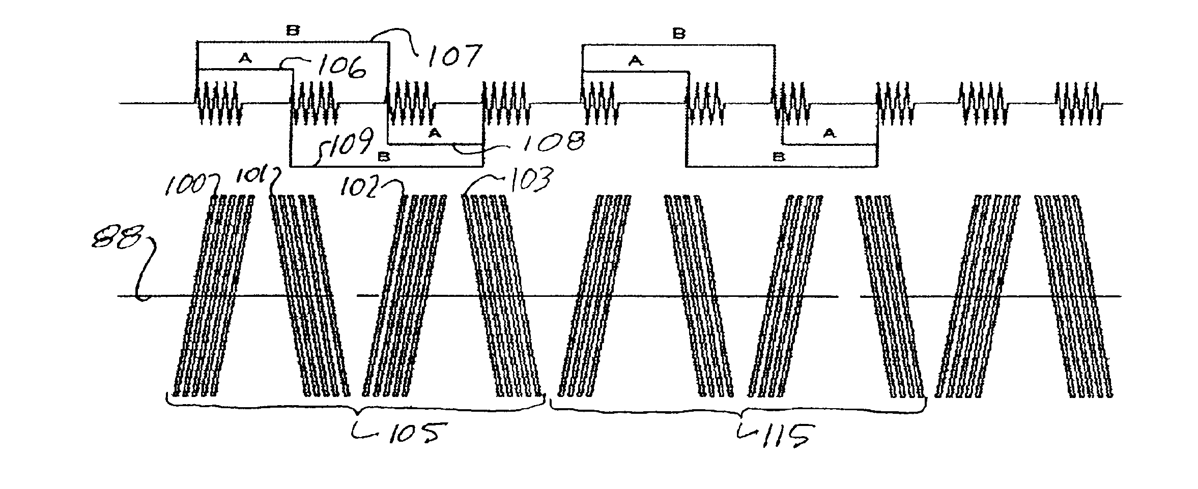
In one embodiment, in the repeating cyclic periodic sequence of transitions, the transitions having parallel azimuthal orientation at one end of one pattern continue with the transitions having parallel azimuthal orientation at the opposite end of the next pattern, such that the continuing transitions are combined to have a different number of transitions than the remainder of the repeating cyclic periodic sequence of transitions, thereby providing synchronization of the repeating cyclic periodic sequence of transitions.
In a further alternative embodiment, the source of timed pulses is coupled to two adjacent write elements and separately coupled to the other write elements. The source of timed pulses provides a first set of timed pulses to all of the spaced apart write elements to simultaneously write to fix the distances between both the “A” and “B” transitions, and additionally provides at least one second timed pulse to only two adjacent write elements to write different numbers of transitions within the pattern, thereby providing synchronization of the repeating cyclic periodic sequence of transitions.

Problems solved by technology

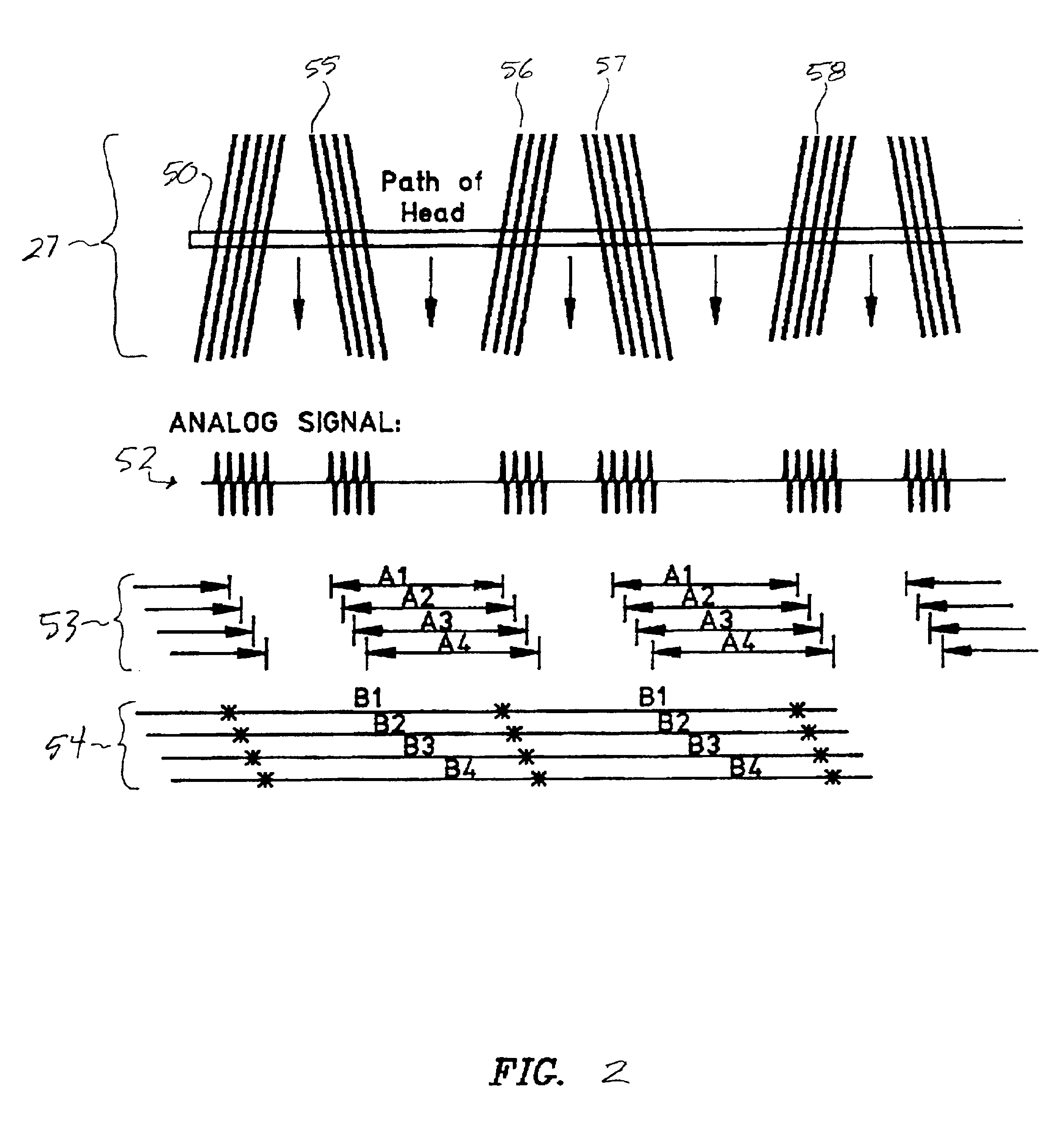
Thus any error in the velocity of the tape in the servo writer results in an error in the “B” distance and hence an error in the lateral position calculated based on pulse “B” pulse timing assuming the correct “B” distance.
Servo writer velocity error introduces a servo position error to the servo track following system and results in data track misregistration.
Further, the data track misregistration becomes worse for data tracks that are positioned such that the distance between “A” pulses is closer to the distance between “B” pulses.

Method used


Image

  • Timing based servo with fixed distances between transitions
  • Timing based servo with fixed distances between transitions
  • Timing based servo with fixed distances between transitions

Examples


Embodiment Construction

This invention is described in preferred embodiments in the following description with reference to the Figures, in which like numbers represent the same or similar elements. While this invention is described in terms of the best mode for achieving this invention's objectives, it will be appreciated by those skilled in the art that variations may be accomplished in view of these teachings without deviating from the spirit or scope of the invention.

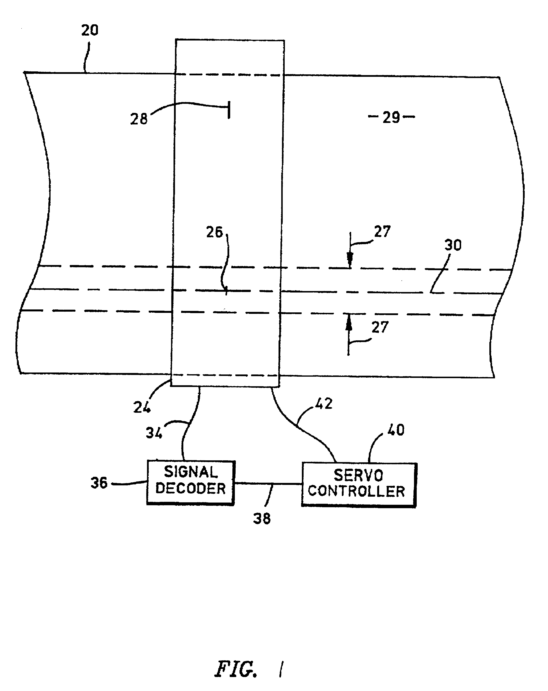
Linear data storage media such as magnetic tape provides a means for physically storing data which may be archived or which may be stored in storage shelves of automated data storage libraries and accessed when required. One method for maximizing the amount of data that can be stored is to maximize the number of parallel tracks on the media, and this is typically accomplished by employing servo systems which provide track following and allow the tracks to be spaced very closely.

Referring to FIG. 1, an example of track following servoing fo...


PUM

PropertyMeasurementUnit
distancesaaaaaaaaaa
distanceaaaaaaaaaa
magnetic transitionsaaaaaaaaaa

Abstract

A servo writer generates a linear servo track timing based servo pattern comprised of transitions that extend laterally of the track. At least three spaced apart write elements, two of parallel azimuthal orientation, and at least one of a different azimuthal orientation, write patterns corresponding to the write elements, fixing both the distance between transitions having different azimuthal orientation, the “A” distance, and the distance between transitions having parallel azimuthal orientation, the “B” distance. The fixed distances provide precise sensing of lateral position based on a measure of time over the “A” distance compared to time over the “B” distance.

Description

FIELD OF THE INVENTIONThis invention relates to servo systems for laterally positioning data heads with respect to linear data storage media, such as magnetic tape, and, more particularly, to linear servo track timing based servo patterns.BACKGROUND OF THE INVENTIONLinear data storage media such as magnetic tape provides a means for physically storing data which may be archived or which may be stored in storage shelves of automated data storage libraries and accessed when required. One method for maximizing the amount of data that can be stored is to maximize the number of parallel tracks on the media, and this is typically accomplished by employing servo systems which provide track following and allow the tracks to be spaced very closely.An example of track following servoing is the provision of prerecorded parallel longitudinal servo tracks that lie between groups of longitudinal data tracks, so that one or more servo heads may read the servo tracks and an accompanying track follo...

Claims


Application Information

Patent Timeline
Patent Type & Authority Patents(United States)
IPC IPC(8): G11B5/584G11B5/265
CPCG11B5/584
Inventor EATON, JAMES HOWARDIMAINO, WAYNE ISAMIPAN, TZONG-SHII
Owner IBM CORP
Learn More