
Destination calling control system and destination calling control method

a control system and control method technology, applied in the field of system and method for controlling a call, can solve problems such as inability to meet, and achieve the effect of quickly discharging

Inactive Publication Date: 2005-04-12
NEC PERSONAL COMPUTERS LTD
View PDF10 Cites 24 Cited by
  • Summary
  • Abstract
  • Description
  • Claims
  • Application Information

AI Technical Summary

Benefits of technology

It is an object of the present invention to provide a destination calling control system and a destination calling control method which feature superior operability and which allow the user to select and specify a destination easily and quickly.
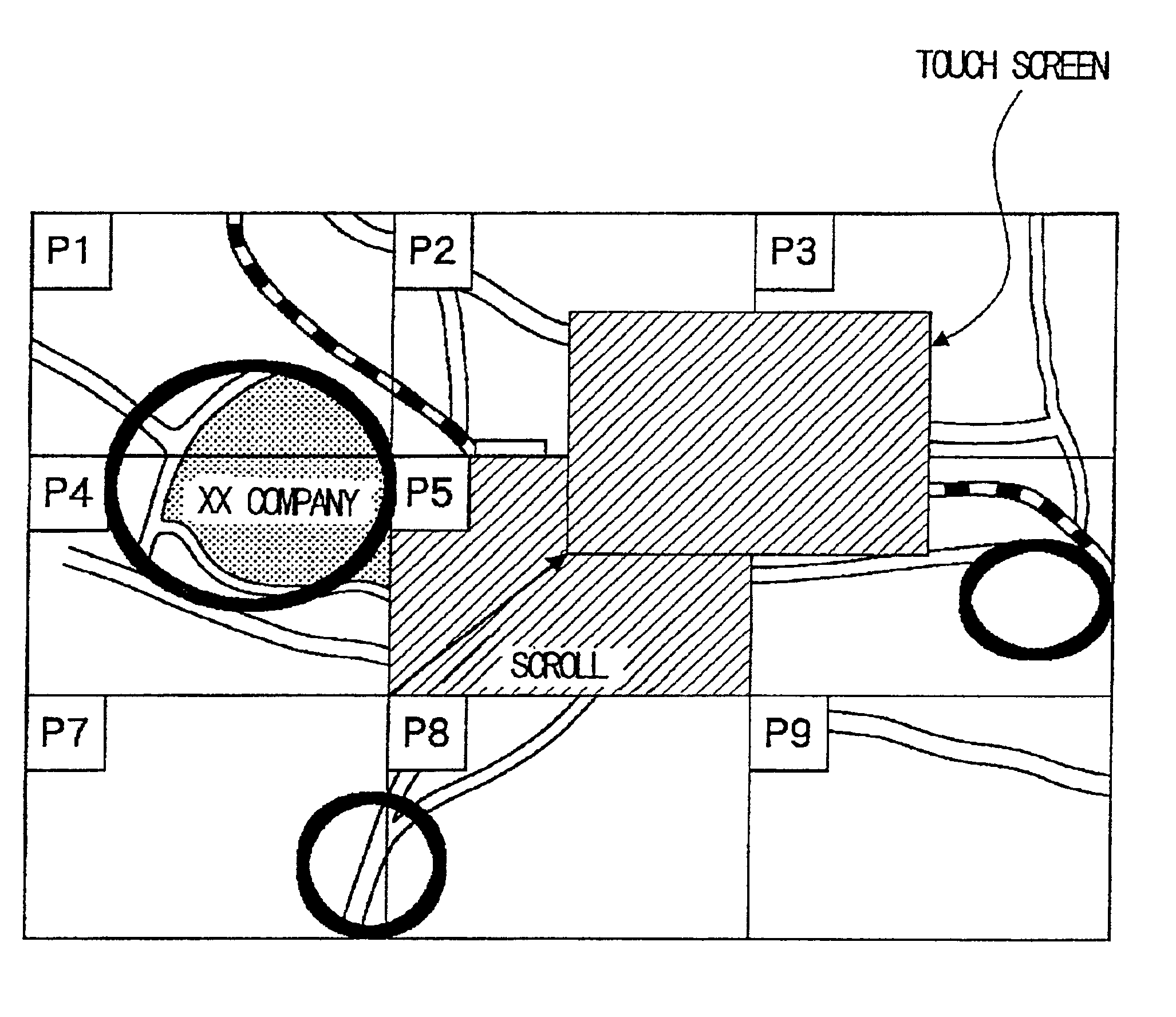
In the above case, the display means may display the title image of a paste image stored in the image storage means as a reference and allow the user to scroll across a whole of the paste image.
In the system in accordance with present invention described above, the user can specify a desired area within the display image as a destination image area and therefore specify a plurality of destination image areas within the display image. The database contains the coordinates of a destination image area and destination data associated therewith. When the user makes a call, the system searches the database for data based on the coordinates of the area specified in the display image and gives the destination data. In this way, the system in accordance with the present invention allows the user to register a destination object included in the display image, as well as its associated destination data, with the database and to make a call to a desired destination object within the display image based on the database. Therefore, the present invention makes it possible for the user to make a call by simply specifying a desired destination object in the display image.
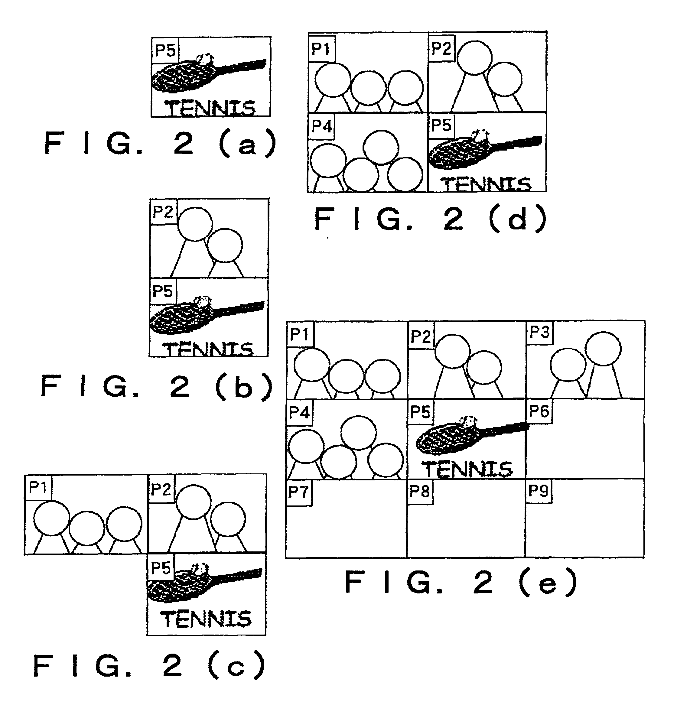
The system in accordance with the present invention stores paste images, each created by pasting a plurality of destination images and a title image, in the storage unit. Because paste images are classified according to title images, a desired destination image may be displayed quickly by searching for the title image. In addition, even when there are many destinations, the system displays the images of the destinations on the screen to allow the user to visually register or select a desired destination. Therefore, as compared with the conventional system in which it takes long to search for a desired destination image, the system in accordance with the present invention searches for it more quickly.

Problems solved by technology

However, according to the technology disclosed in Japanese Patent Kokai Publication JP-A-2-159188, because there is a one-to-one correspondence between destination images and destination telephone numbers and, in addition, stored destination images must be read sequentially from the memory, it takes time to select and specify a desired destination.
However, because destination images and destination telephone numbers are associated on a one-to-one basis according to the technology disclosed in the above publication, this request cannot be met.

Method used


Image

  • Destination calling control system and destination calling control method
  • Destination calling control system and destination calling control method
  • Destination calling control system and destination calling control method

Examples


Embodiment Construction

An embodiment of the present invention will now be described more in detail with reference to the drawings.

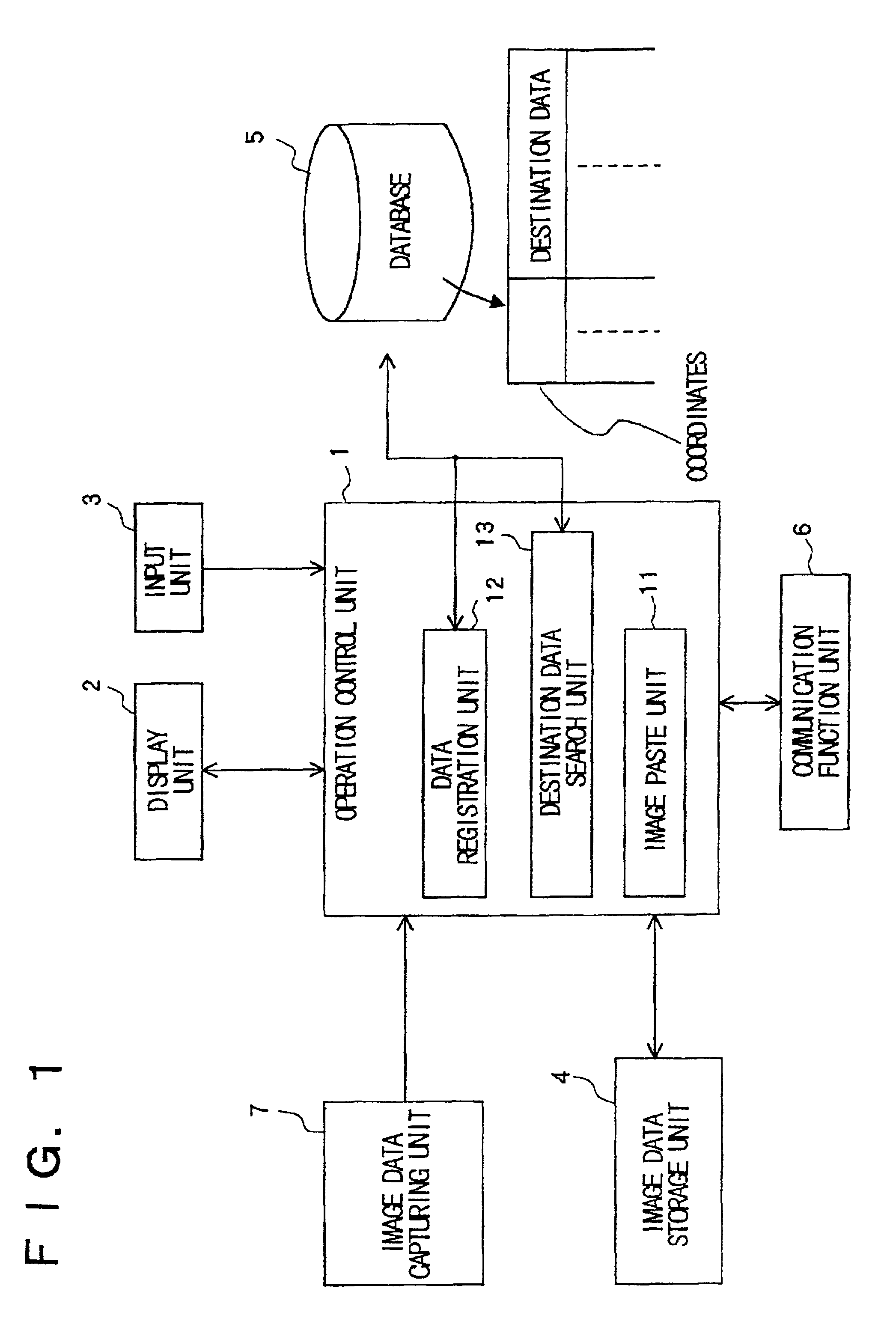
FIG. 1 is a block diagram showing the overall configuration of the embodiment of a destination calling control system according to the present invention. This destination calling control system comprises an operation control unit 1, a display unit 2, an input unit 3, an image data storage unit 4, a database 5 formulated on a memory device, a communication function unit 6, and an image data capturing unit 7.

The image data capturing unit 7 is connected to a camera such as a digital camera to capture an image photographed by the camera. In this embodiment, image data which is of a predetermined size and which contains a plurality of destinations is captured from the camera. The captured image data is sent to the operation control unit 1.

The image data storage unit 4 stores therein paste images for which pasting and editing have been performed by the operation control unit 1. In th...


PUM


Abstract

A destination calling control system comprising a database 5, an image data storage unit 4, a display unit 2 on which image data stored in the image data storage unit 4 is displayed, area specification means for allowing the user to specify a desired area within an image displayed on the display unit 2, an input unit 3 through which the user enters destination data, a data registration unit 12 which calculates the coordinates of a destination image area specified by the above-described area specification means as a destination image area, associates the coordinates with destination data entered from the display unit 2, and registers the correspondence data with the database 5, and a destination data search unit 13 which calculates the coordinates of an area specified by the area specification means as the destination and, based on the calculated coordinates, searches the database 5 for destination data.

Description

FIELD OF THE INVENTIONThe present invention relates to a system and a method for controlling a call to a destination using a database, and more particularly to a destination calling control system and a destination calling control method that are applied to a terminal with the communication function such as a portable data terminal or a cellular phone.BACKGROUND OF THE INVENTIONIn general, a cellular phone has a memory function unit to allow desired destination telephone numbers to be registered therein. Telephone numbers registered in this memory function unit may be displayed on the display panel of a cellular phone. Before making a call, the user may display telephone numbers on the display and select one of them to call a desired party.However, because the display screen of a cellular phone, as well as characters displayed on the screen, is small, there is a problem that, when making a call using the memory function described above, the user finds it difficult to select and spec...

Claims


Application Information

Patent Timeline
IPC IPC(8): H04M1/2745H04M1/274H04M1/27475H04M1/56
CPCH04M1/27455H04M1/27475
Inventor MIYATA, AKIKO
Owner NEC PERSONAL COMPUTERS LTD
Learn More