Lane keep control apparatus and method for automotive vehicle
- Summary
- Abstract
- Description
- Claims
- Application Information
AI Technical Summary
Benefits of technology
Problems solved by technology
Method used
Image
Examples
first embodiment
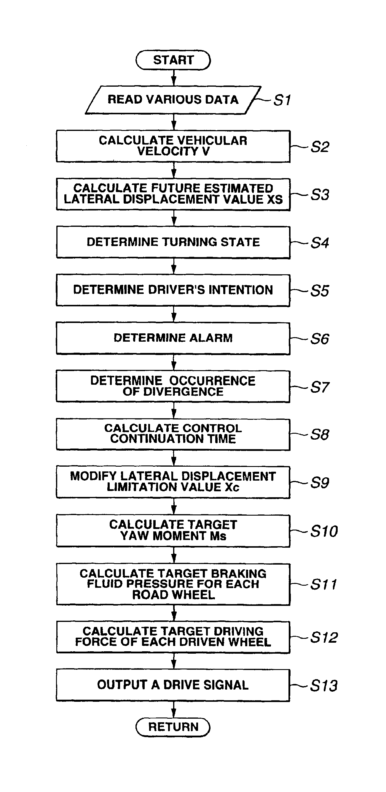
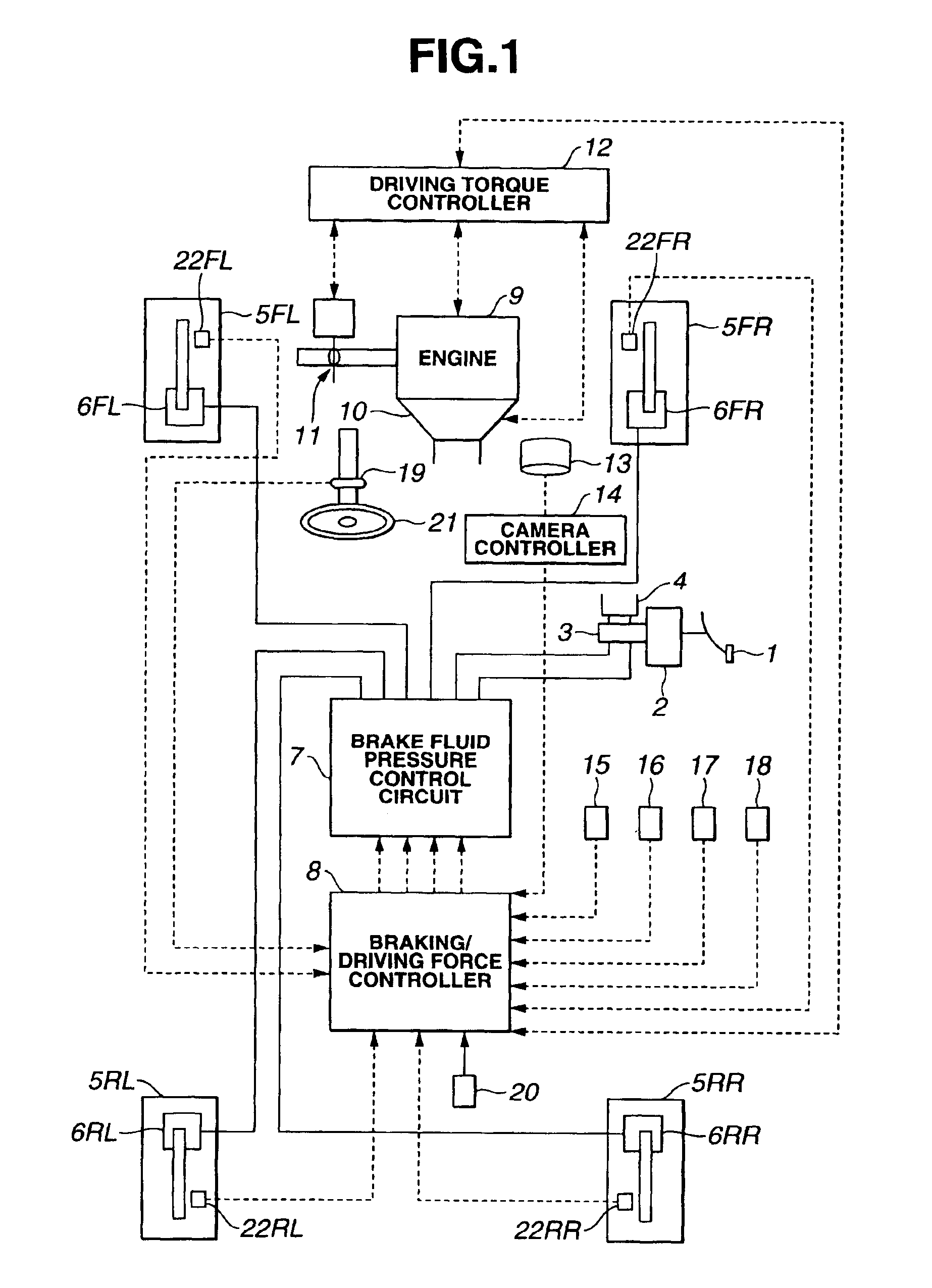
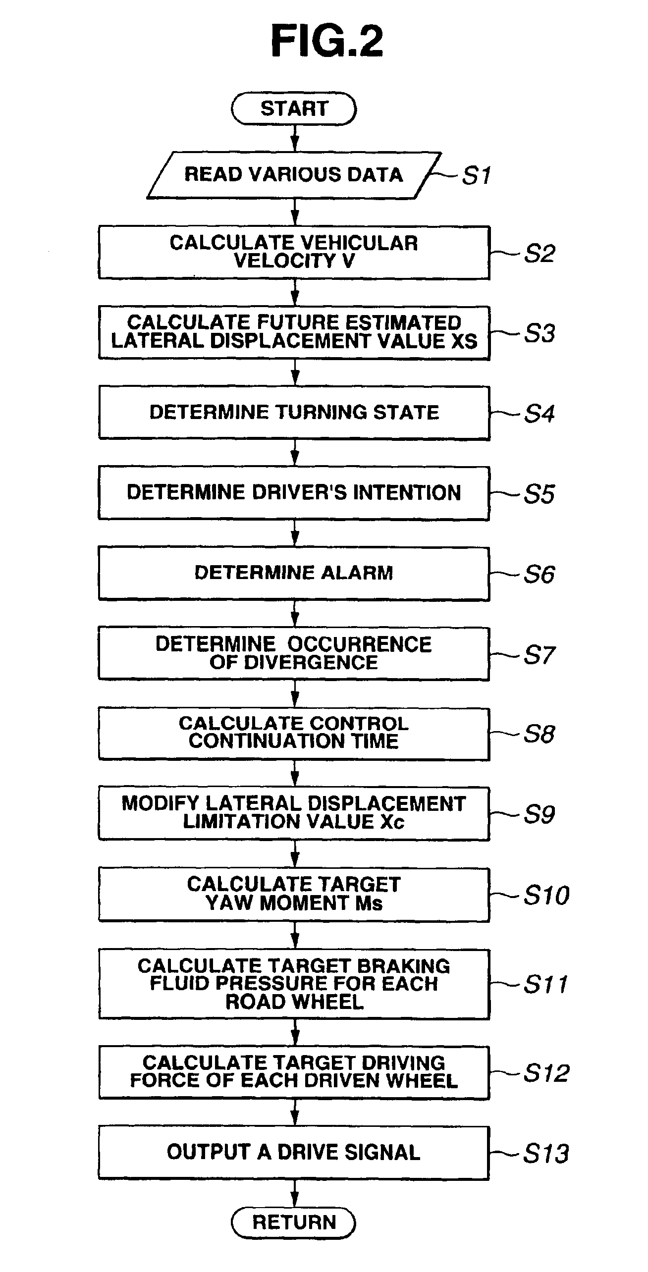
In equation (1), Tt denotes a headway time used to calculate a forward gazing distance and the forward gazing distance is a multiplication of headway time Tt by travel velocity V of the vehicle. In other words, the lateral displacement estimated value from the center of the traffic lane after the headway time Tt indicates future estimated lateral displacement XS. As will be described later, in the first embodiment, there is a possibility that, if future estimated lateral displacement XS becomes equal to or larger than a predetermined lateral displacement limit value, the vehicle would diverge from a traffic lane of the vehicle or the vehicle has a tendency of diverging from the traffic lane.
Next, at a step S4, braking / driving force controller 8 determines a turning state of the vehicle. Specifically, braking / driving force controller 8 determines that the vehicle is quickly turning when an absolute value of lateral acceleration Xg read at step S1 is equal to or larger than a positive...
fifth embodiment
Next, the lane keep control apparatus according to the present invention will be described below.
The rough configuration of the vehicle in the fifth embodiment is generally the same as that shown in FIG. 8 of the third embodiment. In the fifth embodiment, the arithmetic processing carried out in the braking / driving force controller 8 is changed from FIG. 9 concerned with the third embodiment to FIG. 15 concerned with the fifth embodiment.
The arithmetic processing shown in FIG. 15 includes many of the same steps as those described in the third embodiment shown in FIG. 8. The detailed explanation of the same numbered steps as those shown in FIG. 9 will herein be omitted.
In the fifth embodiment, in the arithmetic processing executed in braking / driving force controller 8, the flowchart of FIG. 9 is changed to that shown in FIG. 15.
A new step S27″ shown in FIG. 15 is interposed before step S27 shown in FIG. 9 and step S30 shown in FIG. 9 is changed from step S30″ shown in FIG. 15.
That is...
PUM
 Abstract
Description
Claims
Application Information
 - R&D
- Intellectual Property
- Life Sciences
- Materials
- Tech Scout
- Unparalleled Data Quality
- Higher Quality Content
- 60% Fewer Hallucinations
Browse by: Latest US Patents, China's latest patents, Technical Efficacy Thesaurus, Application Domain, Technology Topic, Popular Technical Reports.
© 2025 PatSnap. All rights reserved.Legal|Privacy policy|Modern Slavery Act Transparency Statement|Sitemap|About US| Contact US: help@patsnap.com


