Fuel cell with ultraphobic surfaces

a fuel cell and ultraphobic technology, applied in the field of fuel cells, can solve the problems of reducing the water affecting the water supply affecting the flow rate of the fuel cell, so as to improve the water drainage, inhibit any tendency, and high degree of repellency of the ultraphobic surface

Inactive Publication Date: 2005-06-28
ENTEGRIS INC
View PDF37 Cites 20 Cited by
  • Summary
  • Abstract
  • Description
  • Claims
  • Application Information

AI Technical Summary

Benefits of technology

[0007]The invention substantially satisfies the aforementioned need of the industry. The invention includes a fuel cell stack apparatus with components having durable ultraphobic surfaces at selected locations where condensation of water may occur so as to improve water drainage within the apparatus. The high degree of repellency of the ultraphobic surfaces substantially inhibits any tendency of water droplets to cling to the surface, thereby significantly improving water drainage within the cell.
[0008]The ultraphobic surface generally includes a substrate portion with a multiplicity of projecting regularly shaped microscale or nanoscale asperities disposed in a regular array so that the surface has a predetermined contact line density measured in meters of contact line per square meter of surface area equal to or greater than a critical contact line density value “ΛL” determined according to the formula: ΛL=-Pγcos⁡(θa,0+ω-90°),where P is a predetermined maximum expected fluid pressure value within the fluid flow channel, γ is the surface tension of the liquid, θα,0 is the experimentally measured true advancing contact angle of the liquid on the asperity material in degrees, and ω is the asperity rise angle. It is generally preferable that the ratio of the cross-sectional dimension of the asperities to the spacing dimension of the asperities is less than or equal to 0.1 so as to optimize repellency of the ultraphobic surface.

Problems solved by technology

A persistent challenge in the design of fuel cells is that of managing water in the cell.
This water is generally produced on the cathode side of the cell, and if allowed to accumulate, may restrict or block the flow of fuel into the cell.
In addition, the temperature differences between the cell and ambient environment may be large so that condensation of water vapor may be caused at times as air moves in and out of the cell during operation.
Neither of these measures has been entirely successful in eliminating cathode flooding and water management problems in fuel cells, however.
In particular, even where low surface energy materials such as PTFE are used in fuel cells, water droplets may cling to bi-polar plates and other surfaces in the cell rather than draining away as desired.

Method used


Image

  • Fuel cell with ultraphobic surfaces
  • Fuel cell with ultraphobic surfaces
  • Fuel cell with ultraphobic surfaces

Examples


example

[0069]Assume an ultraphobic surface is to be provided on a fuel cell bipolar plate. Assume that the maximum expected operating pressure within the fuel cell stack assembly is 5 atmospheres, and that the bipolar plate material has the following characteristics:

θα,0=110°

 θr,0=90°

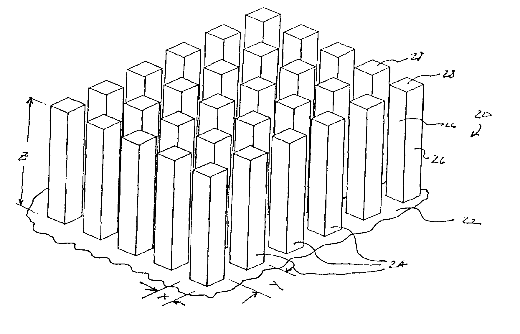
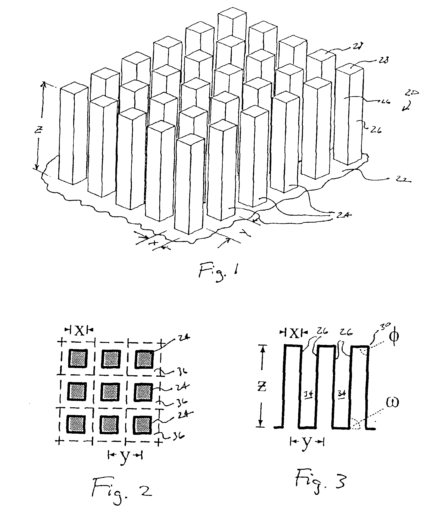
The ultraphobic surface will comprise an array of square posts (ω=90°) on the bipolar plate. Repellancy of the ultraphobic surface is optimized by selecting a small x / y ratio so as to increase the actual advancing and receding contact angles of the water at the fluid contact surface:

Select x / y=λp=0.1

[0070]So that:

θα=λp(θα,0+ω)+(1−λp)θair=180°

and:

[0071]

θr=λpθr,0+(1−λp)θair=171°ΛL=-Pγcos⁡(θa,0+ω-90°)=-51,500⁢ ⁢Pa0.073⁢ ⁢cos⁡(110+90-90)=2,060,000

[0072]Referring to FIG. 17, which is a plot of the relationship between asperity spacing (y) and maximum pressure (P) for various values of x / y, with water as the liquid and with values of θα,0 and θr,0 consistent with material having the described characteristics, it may...


PUM

PropertyMeasurementUnit
electrical potentialaaaaaaaaaa
stationary contact angleaaaaaaaaaa
rise angleaaaaaaaaaa

Abstract

A fuel cell with components having durable ultraphobic surfaces at selected locations where condensation of water may occur. The ultraphobic surface generally includes a substrate portion with a multiplicity of projecting microscale or nanoscale asperities disposed so that the surface has a predetermined contact line density equal to or greater than a critical contact line density.

Description

RELATED APPLICATIONS[0001]This application claims the benefit of U.S. Provisional Patent Application Ser. No. 60 / 462,963 entitled“Ultraphobic Surface for High Pressure Liquids”, filed Apr. 15, 2003, hereby fully incorporated herein by reference.FIELD OF THE INVENTION[0002]This invention relates generally to fuel cells, and more specifically to water management in fuel cells.BACKGROUND OF THE INVENTION[0003]Fuel cell technology has been the subject of much recent research and development activity due to the environmental and long-term fuel supply concerns associated with fossil fuel burning engines and burners. Fuel cell technology generally promises a cleaner source of energy that is sufficiently compact and lightweight to enable use in vehicles. In addition, fuel cells may be located close to the point of energy use in stationary applications so as to greatly reduce the inefficiency associated with energy transmission over long distances.[0004]Although many different fuels and mate...

Claims


Application Information

Patent Timeline
Patent Type & Authority Patents(United States)
IPC IPC(8): B21L3/00H01M2/00H01M2/14H01M2/02H01M8/10H01M8/00H01MH01M8/04H01M8/24
CPCH01M8/0247H01M8/2485H01M8/04291Y02E60/50H01M8/02B21L3/00B82Y30/00H01M8/2484
Inventor EXTRAND, CHARLES W.
Owner ENTEGRIS INC
Why Eureka
Try Eureka