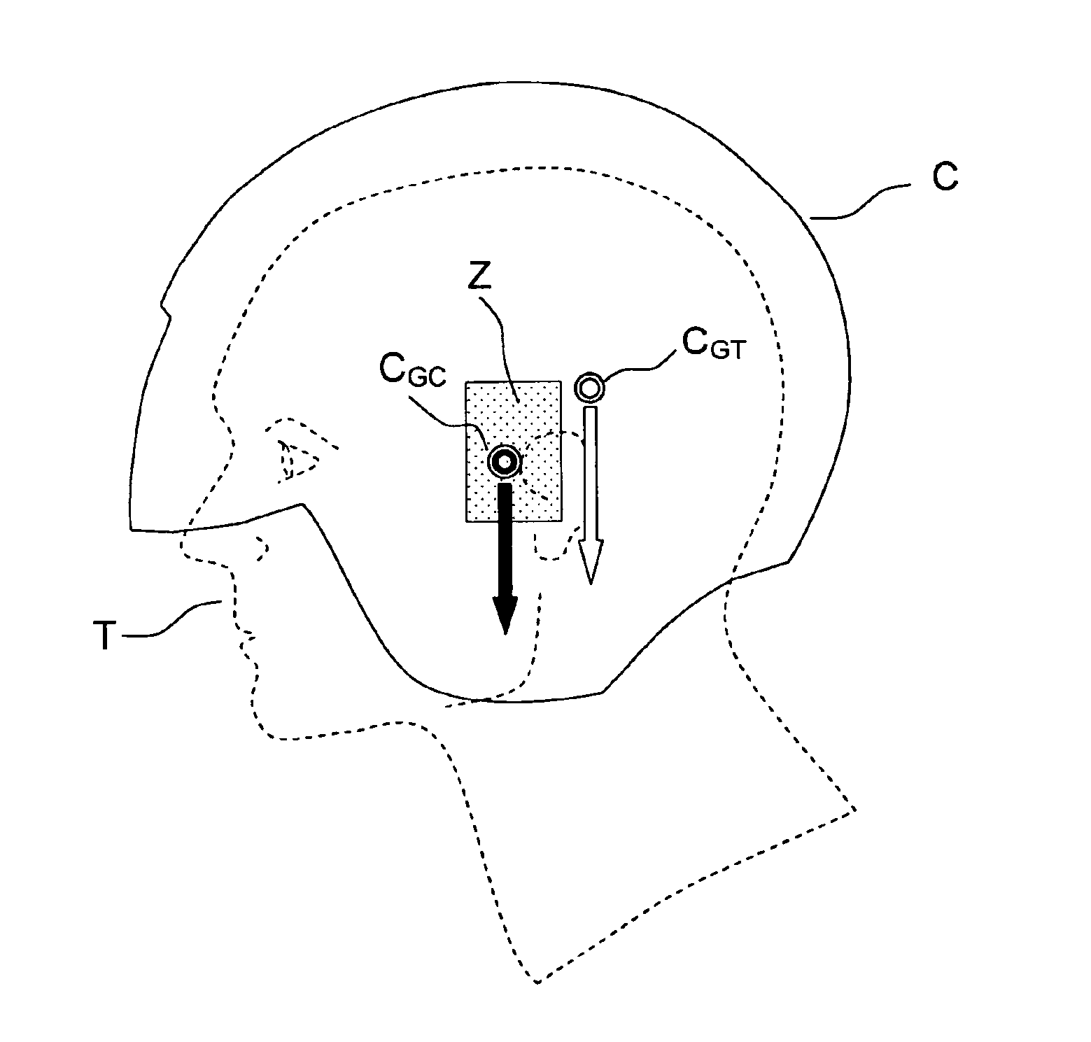
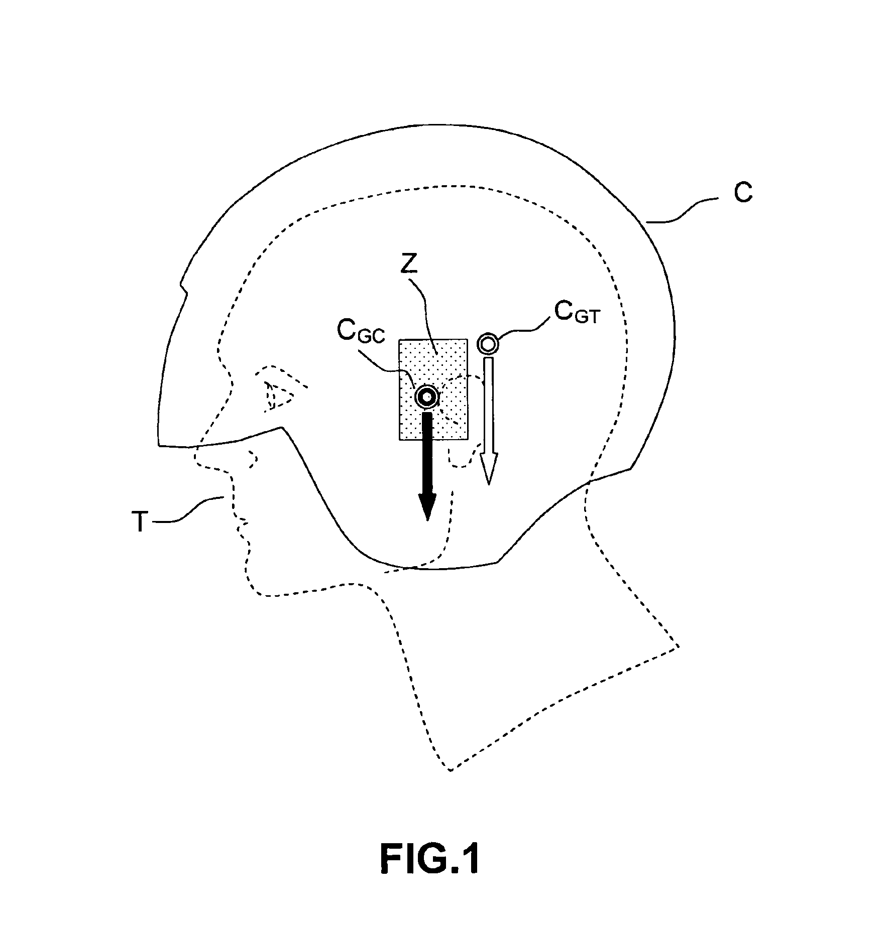
Process for determining the biomechanical compatibility of head equipment
a biomechanical compatibility and head technology, applied in the direction of mechanical measuring arrangements, instruments, using mechanical means, etc., can solve the problems of inaccurate calculation of the center of gravity of the head, the inability to know precisely the mechanical characteristics of the head of the user, and the inability to accurately determine the anatomical particularities of certain users. to achieve the effect of precise calculation of the exact position of the center of gravity
- Summary
- Abstract
- Description
- Claims
- Application Information
AI Technical Summary
Benefits of technology
Problems solved by technology
Method used
Image

Examples
Embodiment Construction
Modern 3D anthropometric techniques are already used for personalizing the head equipment of aircraft crews. This approach avoids the need to fit head equipment with mechanical adjustment means to present the image generated by display systems to the wearer's eyes, such systems adding unnecessarily to the complexity and weight of the helmet.
One simple way of implementing the invention is to use these existing techniques to calculate the center of gravity of the user's head, in which case the basic digital model is a three-dimensional mapping of the external surface of the user's head, the anatomical data then being points on this surface.
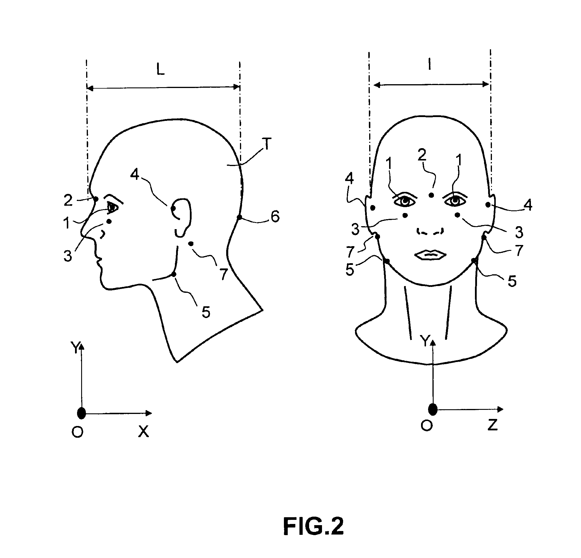
One of the difficult aspects of this mapping is to define a precise triaxial reference frame in which the form of the head is perfectly defined, in order to be able to calculate the centers of gravity of the head and the equipment in the same reference frame. The simplest approach is to define identifiable anthropometric points, said points enabling...
PUM
 Abstract
Description
Claims
Application Information