
Signal modification based on continuous time warping for low bit rate CELP coding

Inactive Publication Date: 2005-04-12
MICROSOFT TECH LICENSING LLC
View PDF14 Cites 150 Cited by
  • Summary
  • Abstract
  • Description
  • Claims
  • Application Information

AI Technical Summary

Benefits of technology

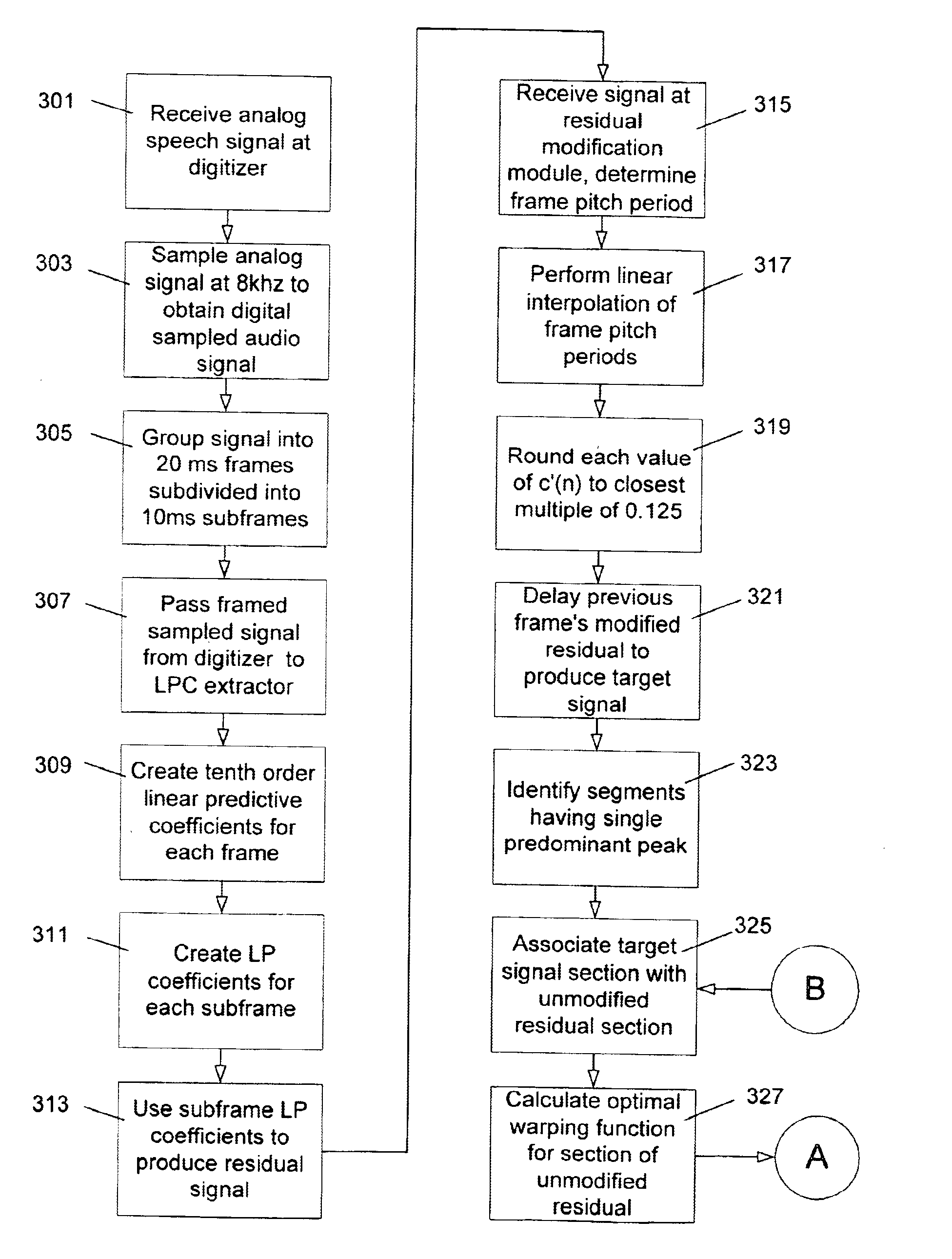
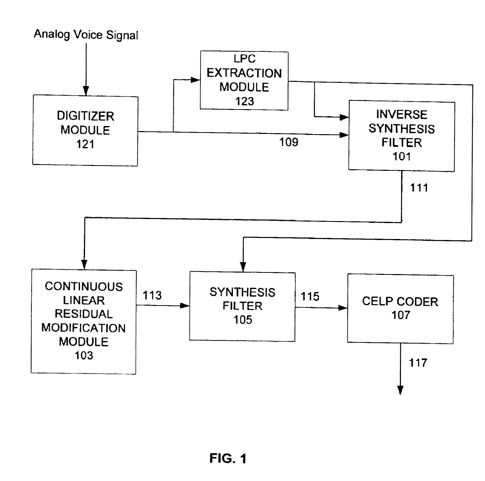
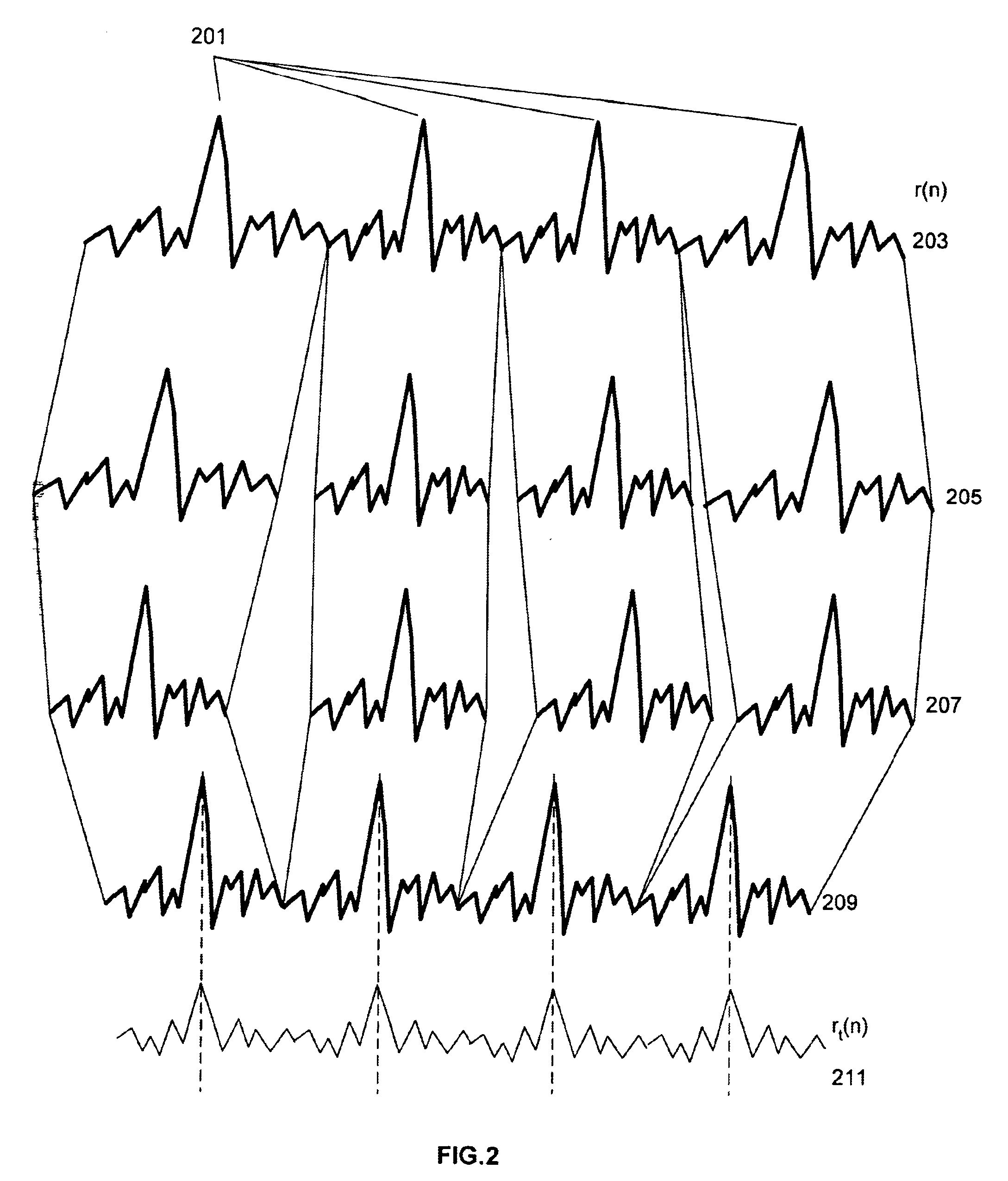
The invention employs a continuous, rather than simply piece-wise continuous, time warp contour to modify the original residual signal to match a synthetic contour, thus avoiding edge shifting effects prevalent in the prior art. In particular, the warp contour employed within the invention is continuous, i.e. lacking spatial jumps or discontinuities, and does not invert or overly distend the positions of adjacent end points in adjacent frames.

Problems solved by technology

Channels and media usable for the transmission and / or storage of digital voice are often of limited capacity, and grow more so every day.
Available digital voice coding techniques span a spectrum from inefficient techniques that employ no compression to efficient techniques that achieve compression ratios of four or greater.
Waveform coders actually attempt to describe the sound wave itself and typically do not achieve high rates of compression.
Voice coders, or vocoders, take into account the source and peculiarities of human speech rather than simply attempting to map the resultant sound wave, and accordingly may achieve much higher compression rates, albeit at the expense of increased computational complexity.
However, as the available capacity or bandwidth decreases, the richness of the CELP codebooks necessarily decreases.
Problems with this approach include the fact that as an artifact of the particular warping methodology, certain portions of the original signal may be omitted or repeated.
These artifacts produce an audible distortion in the final reproduced speech.
All pitch warping approaches suggested in the past have suffered similar shortcomings, including a reduction in quality due to the shifting of segment edges, causing omissions and repeats of the original signal.

Method used


Image

  • Signal modification based on continuous time warping for low bit rate CELP coding
  • Signal modification based on continuous time warping for low bit rate CELP coding
  • Signal modification based on continuous time warping for low bit rate CELP coding

Examples


Embodiment Construction

In the description that follows, the invention will be described with reference to acts and symbolic representations of operations that are performed by one or more computers, unless otherwise indicated. As such, it will be understood that such acts and operations, which are at times referred to as being computer-executed, include the manipulation by the processing unit of the computer of electrical signals representing data in a structured form. This manipulation transforms the data or maintains it at locations in the memory system of the computer, which reconfigures or otherwise alters the operation of the computer in a manner well understood by those skilled in the art. The data structures where data is maintained are physical locations of the memory that have particular properties defined by the format of the data. However, while the invention is being described in the foregoing context, it is not meant to be limiting as those of skill in the art will appreciate that various of ...


PUM


Abstract

A signal modification technique facilitates compact voice coding by employing a continuous, rather than piece-wise continuous, time warp contour to modify an original residual signal to match an idealized contour, avoiding edge effects caused by prior art techniques. Warping is executed using a continuous warp contour lacking spatial discontinuities which does not invert or overly distend the positions of adjacent end points in adjacent frames. The linear shift implemented by the warp contour is derived via quadratic approximation or other method, to reduce the complexity of coding to allow for practical and economical implementation. In particular, the algorithm for determining the warp contour uses only a subset of possible contours contained within a sub-range of the range of possible contours. The relative correlation strengths from these contours are modeled as points on a polynomial trace and the optimum warp contour is calculated by maximizing the modeling function.

Description

TECHNICAL FIELDThis invention relates generally to speech coding techniques and, more particularly, relates to techniques for modifying a signal to aid in coding the signal via a low bit-rate coding technique such as codebook excited linear prediction (CELP) coding.BACKGROUND OF THE INVENTIONIn today's highly verbal and highly interactive technical climate, it is often necessary or desirable to transmit human voice electronically from one point to another, sometimes over great distance, and often over channels of limited bandwidth. For example, conversations via cell phone links or via the Internet or other digital electronic networks are now commonplace. Likewise, it is often useful to digitally store human voice, such as on the hard drive of a computer, or in the volatile or nonvolatile memory of a digital recording device. For example, digitally stored human voice may be replayed as part of a telephone answering protocol or an audio presentation.Channels and media usable for the ...

Claims


Application Information

Patent Timeline
IPC IPC(8): G10L19/08G10L19/00G10L15/12G10L15/00G10L19/12G10L19/04H03M7/30
CPCG10L19/08G10L15/12G10L19/00
Inventor RAO, AJIT V.
Owner MICROSOFT TECH LICENSING LLC
Learn More