Rotor removal tool and method

a technology for removing tools and rotors, applied in metal-working equipment, metal-working equipment, manufacturing tools, etc., can solve problems such as difficult to remove/b> from the hub, damage to various components of the wheel assembly, and especially difficult to remove from the hub, so as to reduce the likelihood of damage to components during removal, the effect of fast and safe removal

Inactive Publication Date: 2005-04-19
CHRISTOPHER MARK J
View PDF10 Cites 7 Cited by
  • Summary
  • Abstract
  • Description
  • Claims
  • Application Information

AI Technical Summary

Benefits of technology

[0009]The present invention provides an improved tool for, and method of, removing a component from an assembly, that is fast, safe, and reduces the likelihood of damaging the component during removal. The tool and method of the present invention are especially useful for removing a brake rotor from a hub of a vehicle.

Problems solved by technology

This problem is especially pronounced when the vehicle is older and the brake assembly components have a build-up of dirt and / or corrosion.
The rotor 14 may also be difficult to remove from the hub 10 when the vehicle has been recently driven, due to thermal expansion of the hub 10.
However, this technique is likely to damage various components of the wheel assembly, and is, therefore, unsatisfactory.
However, brake rotors on most vehicles are not provided with these threaded removal holes.

Method used


Image

  • Rotor removal tool and method
  • Rotor removal tool and method
  • Rotor removal tool and method

Examples


Embodiment Construction

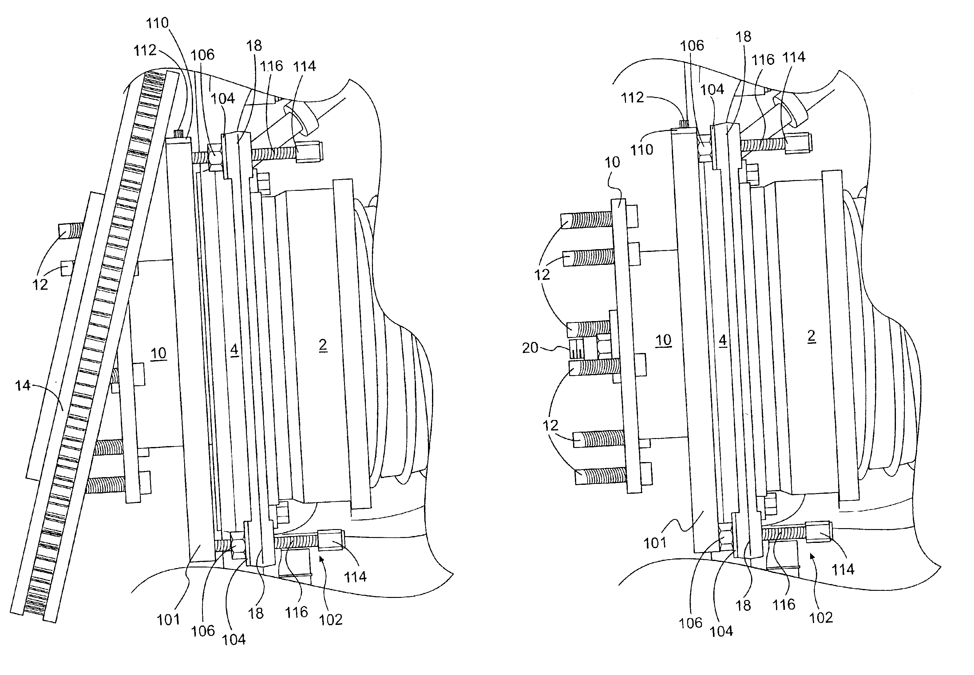
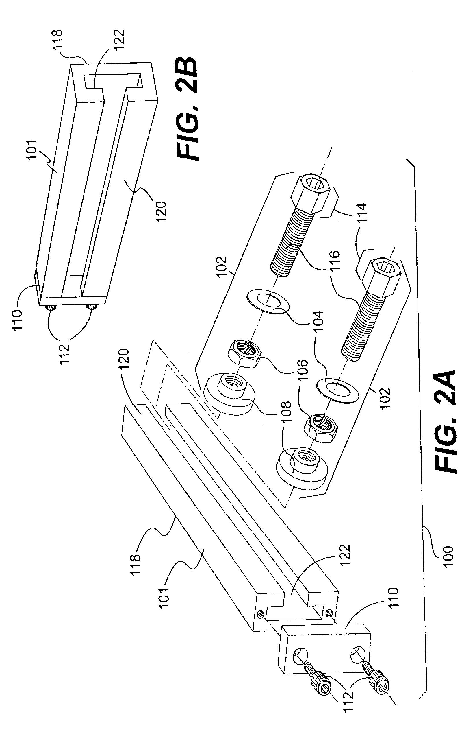
[0023]In general, the present invention relates to a tool used to remove a component from an assembly by providing a force between the component to be removed and the assembly. As illustrated in FIGS. 2A and 2B, the tool 100 generally comprises an elongated bar 101 and a pressing device 102. In operation, the tool 100 is attached, via the pressing device 102, to the assembly. The pressing device 102 is then attached to the elongated bar 101, and adjusted to provide a pressing force between the assembly and a component to be removed. The elongated bar 101 abuts the component to be removed from the assembly and distributes the pressing force applied by the pressing device 102 over a larger area of the component that is being removed.

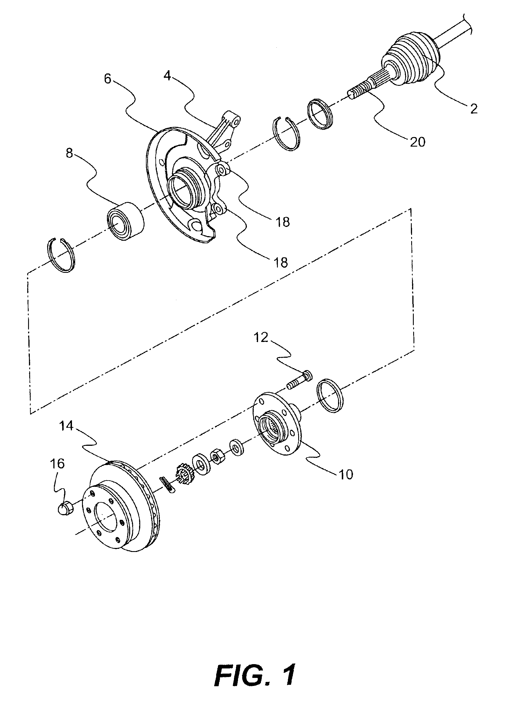
[0024]The tool may be adapted to remove different components from various different assemblies. However, one particular application to which the tool is especially well suited, is the removal of a disc brake rotor from a brake assembly of a front- or four-...


PUM

PropertyMeasurementUnit
forceaaaaaaaaaa
shapeaaaaaaaaaa
inner diameteraaaaaaaaaa

Abstract

A tool for, and method of, removing a first component, such as a disc brake rotor, from an assembly, such as a disc brake assembly. The tool includes an elongated bar and a pressing device. The elongated bar has a pressing surface for pressing against the first component, and a backing surface opposite the pressing surface. The pressing device is connectable to the backing surface of the elongated bar. The pressing device is adjustable to engage a second component that is fixed to the assembly, in order to apply a force between the first component and the second component, to thereby remove the first component from the assembly.

Description

FIELD OF THE INVENTION[0001]The present invention relates generally to a tool used to remove a component from an assembly by providing a force between the component to be removed and the assembly. The present invention also relates to a method of removing a component from an assembly using a tool.BACKGROUND OF THE INVENTION[0002]Prior to the present invention, there was no suitable way to remove the disc brake rotor from the hub of some vehicles.[0003]An exploded view of a front disc brake assembly of a conventional front- or four-wheel drive vehicle is shown in FIG. 1. The brake assembly generally comprises a steering knuckle 4, which is pivotally attached to the vehicle suspension to allow a vehicle wheel (not shown) to turn. An axle shaft or drive shaft 2 extends through an opening in the center of the steering knuckle 4, such that a distal end 20 of the drive shaft projects outwardly from the steering knuckle 4. The distal end 20 of the axle shaft 2 has splines formed in its out...

Claims


Application Information

Patent Timeline
Patent Type & Authority Patents(United States)
IPC IPC(8): B25B27/00B25B27/02
CPCB25B27/0035B25B27/023Y10T29/49721Y10T29/53848Y10T29/53448Y10T29/53683Y10T29/49822Y10T29/53891
Inventor CHRISTOPHER, MARK J.
Owner CHRISTOPHER MARK J
Why Eureka
Try Eureka