Combustor with turbulence producing device

a turbulence producing device and combustor technology, applied in the field of combustor, can solve the problems of limited enhancement of mixing action, unstable combustion, and vibration of combustion, and achieve the effects of reducing the influence of air capacity and the length of an air column positioned upstream of the turbulence producing body, enhancing the mixing action of fuel and air, and preventing the occurrence of nox

Inactive Publication Date: 2005-04-19
MITSUBISHI HITACHIPOWER SYST LTD
View PDF8 Cites 41 Cited by
  • Summary
  • Abstract
  • Description
  • Claims
  • Application Information

AI Technical Summary

Benefits of technology

[0013]Namely, according to the first embodiment of the present invention, a turbulence producing body produces turbulence in the airflow in the vicinity of the fuel injection port. Accordingly, the air can be mixed with fuel while the air turbulence is maintained. Therefore, the mixing action of fuel and air can be enhanced. The occurrence of a hot spot is prevented by uniformly mixing air with fuel, and thus the occurrence of NOx can be prevented. Further, the turbulence producing body also functions as a pressure losing body. Accordingly, the velocity fluctuation in the combustion vibration can be absorbed by producing the flow resistance. Thus, the influences of the capacity of air and the length of an air column positioned upstream of the turbulence producing body are reduced, and the amplitude of the velocity fluctuation is decreased in the pre-mixing nozzle. Therefore, concentration fluctuations of fuel is decreased in the pre-mixing nozzle, and the occurrence of the combustion vibration is prevented.

Problems solved by technology

However, the number of the hollow columns and the number of injection ports are physically limited and, thus, the enhancement of the mixing action is limited.
Consequently, combustion vibration occurs.
The combustion becomes unstable due to the combustion vibration, and the combustor cannot be driven stably.
Therefore, there is a possibility that an air turbulence occurred by the velocity fluctuation absorbing member in the inlet portion is decreased in the vicinity of the mixing chamber, or completely disappears in the vicinity of the mixing chamber.
Further, when the number of hollow columns is increased, it is difficult to supply air to the mixing chamber because the hollow columns 250 interrupt the airflow.

Method used


Image

  • Combustor with turbulence producing device
  • Combustor with turbulence producing device
  • Combustor with turbulence producing device

Examples


first embodiment

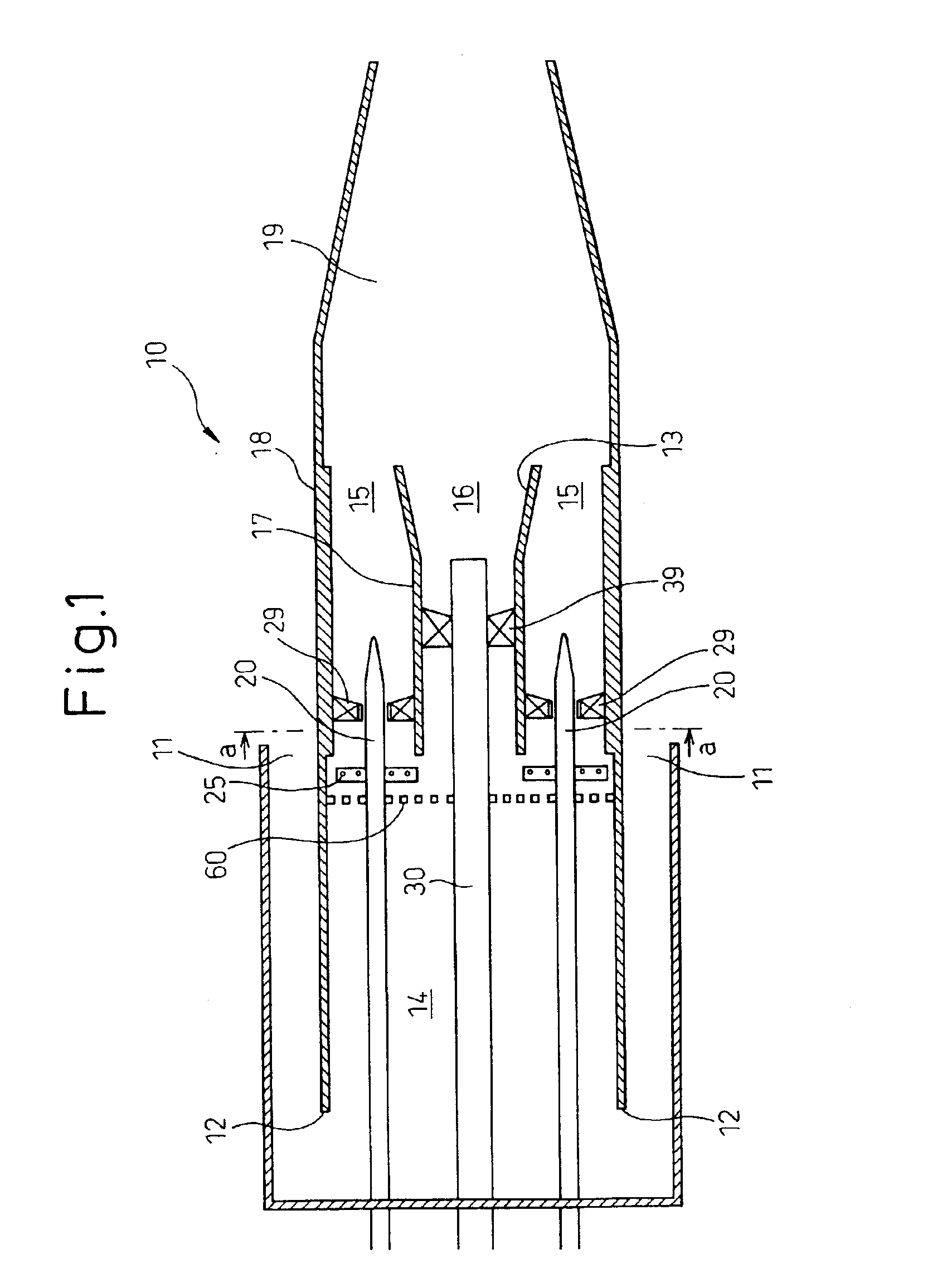
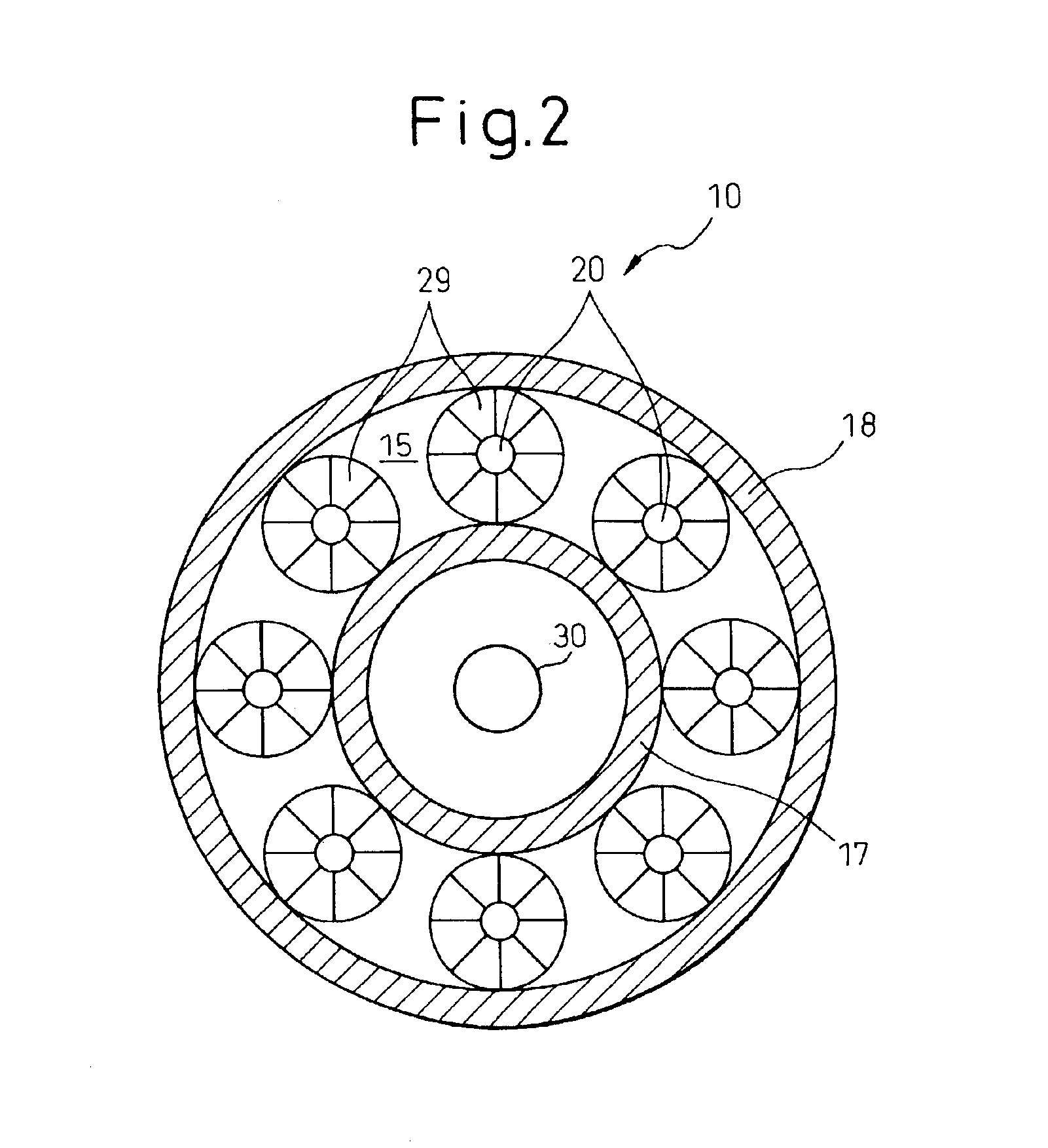
[0030]FIG. 1 shows a longitudinal partially sectional view of a combustor according to the present invention. FIG. 2 is a sectional view taken along the line a—a in FIG. 1. Similar to the above-described embodiment, a pilot nozzle 30 is provided on a center axis of an inner tube 18 of a combustor 10. As can be seen from FIG. 2, a plurality of fuel nozzles 20 are equally spaced in a circumferential direction around the pilot nozzle 30. A swirl vane or a swirler 29 is disposed around a rodlike body of the fuel nozzle 20. A plurality of hollow columns 25 are provided on the fuel nozzle 20. The hollow columns 25 radially and outwardly extend from the sidewall of the fuel nozzle, and are connected to the fuel nozzle 20. A plurality of injection ports 26 are provided in each hollow column 25 so that the fuel that flows through the fuel nozzle 20 is introduced into the hollow column 25 and, then, is injected from these injection ports toward a tip end of the fuel nozzle. Further, a mixing ...

second embodiment

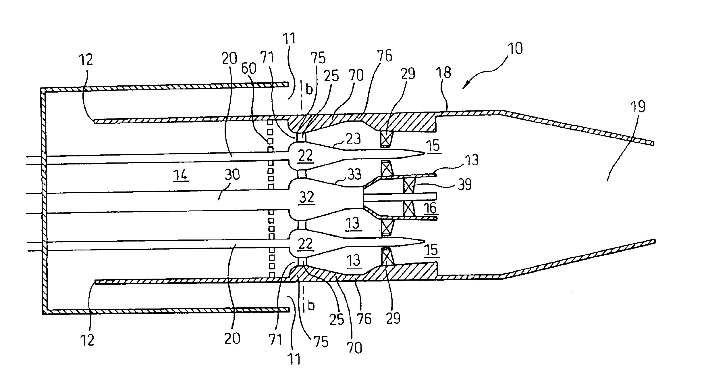
[0037]FIG. 6 is a longitudinal direction partially sectional view of a combustor according to the present invention. FIG. 7 is an enlarged view of a fuel nozzle of a combustor shown in FIG. 6. FIG. 8 is a sectional view taken along the line b—b in FIG. 6. As shown in FIG. 6, a diffuser portion 70 is provided in the inner tube 18 of the combustor 10. The diffuser portion 70 contains a narrow portion 75 that is narrow in the radial direction and a wide portion 76 that is wide in the radial direction, and an inclined portion 77 smoothly connects the narrow portion 75 to the wide portion 76. The fuel nozzle 20 and the pilot nozzle 30 have projections 22, 32, respectively. These projections 22, 32 are substantially shaped like a cone that tapers down in the downstream direction of the airflow, and have inclined portions 23, 33, respectively. As can be seen from FIG. 6, an annular chamber 13 is defined by an inner wall of the diffuser portion 70 and an outer wall of the pilot nozzle 30. T...


PUM


Abstract

The present invention relates to a gas turbine combustor comprising an air passage to supply air to the inside; and a fuel nozzle which is provided with an injection port to inject fuel and disposed in the air passage, wherein a turbulence producing means adjacent to the injection port of the fuel nozzle is provided in the air passage. Further, the present invention relates to a gas turbine combustor comprising an air passage to supply air to the inside; and a fuel nozzle which is provided with an injection port to inject fuel and disposed in the air passage, wherein a diffuser portion is provided in the air passage, and the diffuser portion causes the cross-sectional area of a part of the air passage positioned in the vicinity of the injection port to be smaller than that of a downstream portion of the air passage positioned downstream from the injection port in the direction of the airflow. Thus, the mixing action of fuel and air can be enhanced, and combustion vibration can be prevented.

Description

TECHNICAL FIELD[0001]The present invention relates to a combustor, and particularly, to a gas turbine combustor used for a gas turbine.BACKGROUND ART[0002]FIG. 13 shows a longitudinal sectional view of a prior art and is the combustor containing a fuel nozzle disclosed in Japanese Unexamined Patent Publication (Kokai) No. 6-2848. As shown in FIG. 13, a pilot nozzle 300 is provided on a center axis of an inner tube 180 of a combustor 100. A plurality of fuel nozzles 200 which extend substantially in parallel with the pilot nozzle 300 are equally spaced in a circumferential direction around the pilot nozzle 300. Fuel is supplied to the pilot nozzle 300 and fuel nozzles 200. A swirl vane or a swirler 290 is disposed around a rodlike body of the fuel nozzle 200. A plurality of hollow columns 250 which radially and outwardly extend from the sidewall of the fuel nozzle 200 are provided on the fuel nozzle 200. The hollow columns 250 are connected to the fuel nozzle 200. A plurality of inje...

Claims


Application Information

Patent Timeline
Patent Type & Authority Patents(United States)
IPC IPC(8): F23D14/70F23D14/46F23R3/14F23R3/28F23R3/04F23D14/02F23R3/10F23R3/32F23R3/34
CPCF23D14/70F23R3/286F23R3/14F23R2900/00014
Inventor SAITOH, KEIJIRO
Owner MITSUBISHI HITACHIPOWER SYST LTD
Why Eureka
Try Eureka