Pneumatic rotary tool

Inactive Publication Date: 2005-04-19
S P AIR
View PDF25 Cites 59 Cited by
  • Summary
  • Abstract
  • Description
  • Claims
  • Application Information

AI Technical Summary

Benefits of technology

[0004]Among the several objects and features of the present invention may be noted the provision of a pneumatic rotary tool which weighs and costs less due to plastic components; the provision

Problems solved by technology

These tools are strong and durable due to their metallic construction, although the all-metal construction makes them both somewhat heavy and costly.
One difficulty in the design of such a tool is the reduced rigid

Method used


Image

  • Pneumatic rotary tool
  • Pneumatic rotary tool
  • Pneumatic rotary tool

Examples


Embodiment Construction

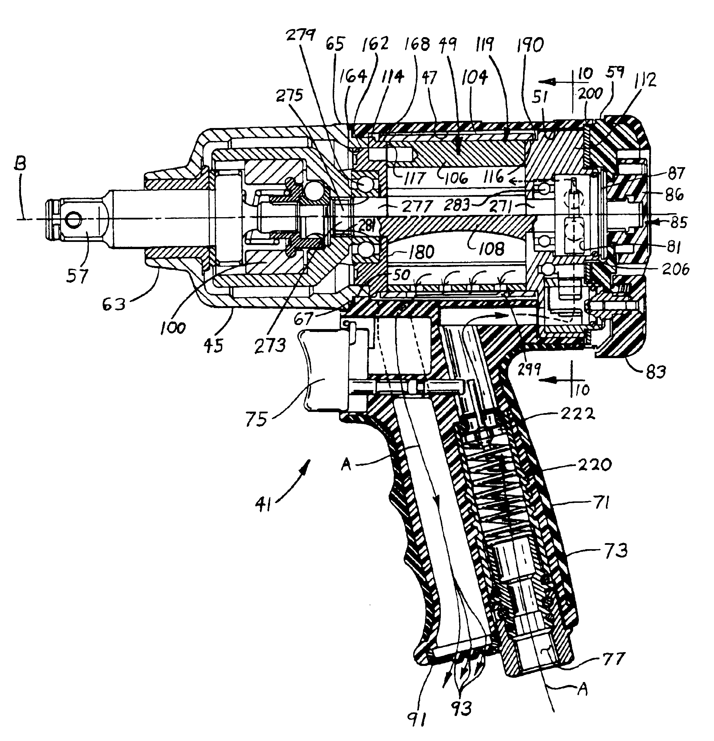
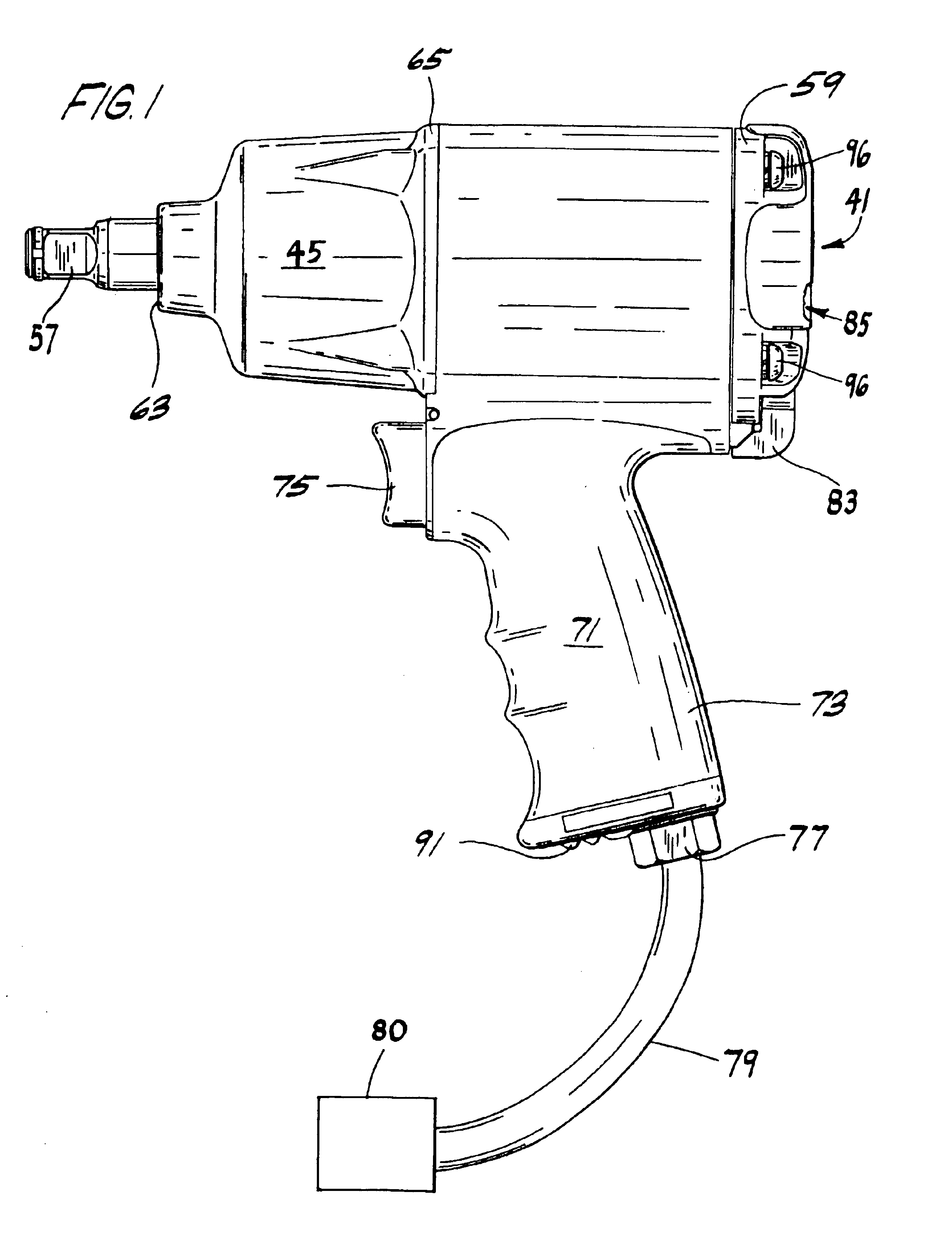
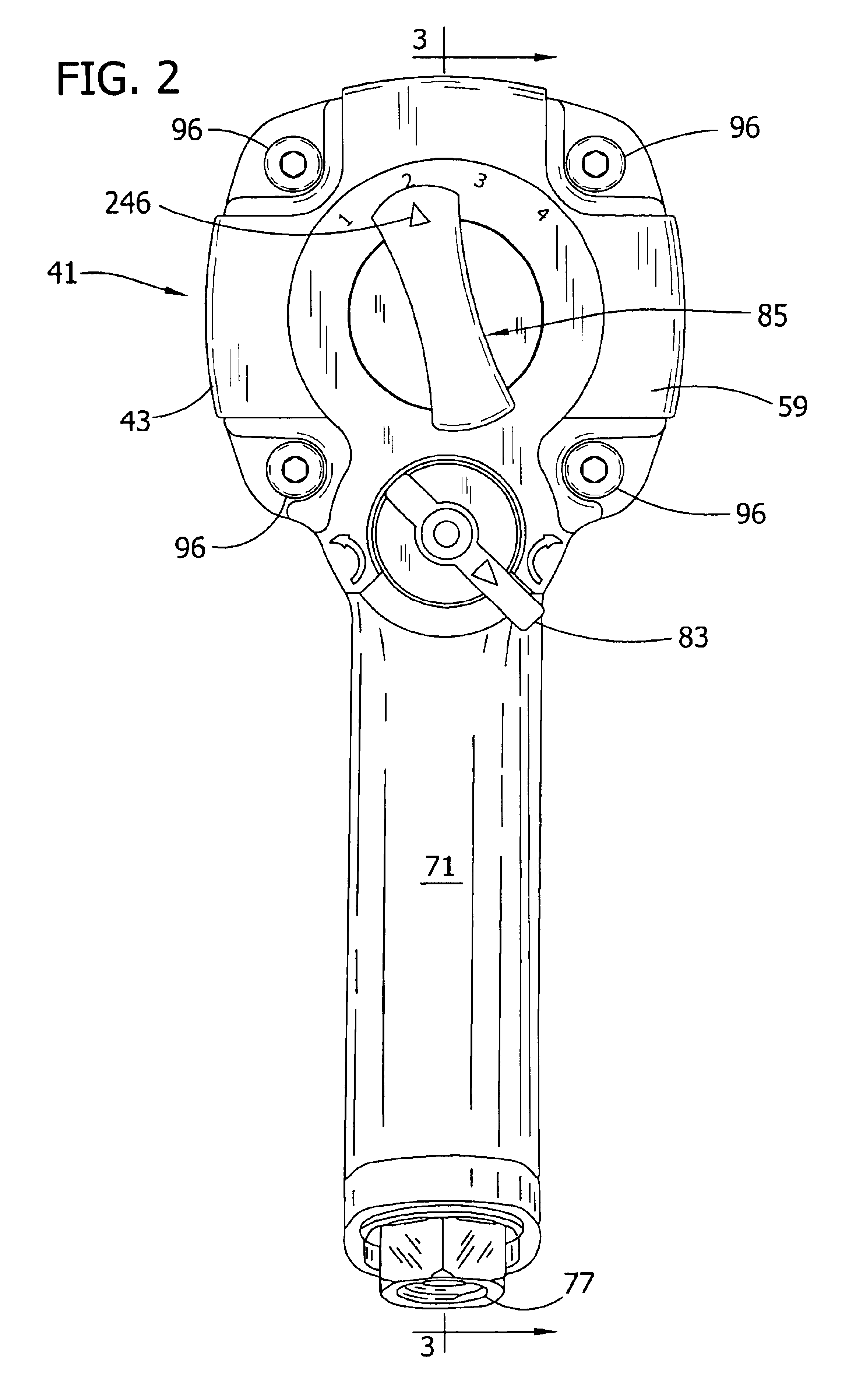
[0039]Referring now to the drawings and specifically to FIGS. 1-3, a pneumatic rotary tool of an embodiment of the present invention is generally indicated at 41. The tool includes a housing 43, a Maurer Mechanism casing 45 at the front of the housing and a motor receptacle 47 (FIG. 3) disposed rearwardly of the casing and sized and shaped for receiving an air motor, generally indicated at 49. The receptacle 47 has a front end 50 and an open rear end 51. The tool 41 also includes an output shaft 57 extending from the front of the housing 43 and an end cover 59 located at the rear end 51 of the receptacle 47 to close the receptacle. The end cover 59 is formed separately from the receptacle 47. The casing 45 may be considered part of the housing 43, due to the generally uniform interface between the housing and casing, which creates the appearance of one continuous profile when viewing the tool 41. The output shaft 57 extends from a front end 63 of the Maurer Mechanism casing 45. A ba...


PUM

PropertyMeasurementUnit
Pressureaaaaaaaaaa
Areaaaaaaaaaaa
Torqueaaaaaaaaaa

Abstract

Generally, a pneumatic rotary tool of the present invention comprises a housing formed of a plastic material and includes a motor receptacle having a front end and an open rear end. An air motor is disposed within the motor receptacle of the housing. An air inlet passage extends to the motor for delivering pressurized air to the motor to power the motor to drive an output shaft. An end plate of the motor has air passaging formed therein, at least part of the air passaging defining a portion of the air inlet passage. A torque selector is at least partially received in the end plate and includes a portion disposed in the air passaging defined in the end plate and at least partially blocking the flow of air in the air passaging except through the portion of the torque selector.

Description

BACKGROUND OF THE INVENTION[0001]This invention generally relates to pneumatic rotary tools and more particularly to an improved pneumatic rotary tool having a plastic housing and a variable torque design for efficient use of pressurized air.[0002]The invention is especially concerned with a powered tool that rotates an output shaft with a socket for turning a fastener element such as a bolt or nut. Tools of this type are frequently used in automotive repair and industrial applications. Most pneumatic rotary tools comprise a metallic outer housing with multiple metallic internal parts. These tools are strong and durable due to their metallic construction, although the all-metal construction makes them both somewhat heavy and costly. Pressurized air flowing through the tool powers tools of this type. As the air expands within the tool, it induces motion of an internal motor, powering the tool.[0003]It is an aim of tool manufacturers to provide a pneumatic rotary tool that is as durab...

Claims


Application Information

Patent Timeline
IPC IPC(8): B25B21/02B25B23/14B25B21/00B25B23/145B25F5/00
CPCB25B21/00B25F5/00B25B23/145B25B21/02
Inventor IZUMISAWA, OSAMU
Owner S P AIR
Why Eureka
Try Eureka