
Cover ejection and fin deployment system for a gun-launched projectile

a technology of cover ejection and fins, which is applied in the direction of weapons, projectiles, wing adjustments, etc., can solve the problem that the deployment speed of fins cannot reach a level

Inactive Publication Date: 2005-04-19
GEN DYNAMICS ORDNANCE & TACTICAL SYST +1
View PDF6 Cites 135 Cited by
  • Summary
  • Abstract
  • Description
  • Claims
  • Application Information

AI Technical Summary

Benefits of technology

"The invention is about a system for controlling, storing, and deploying the steering fins of a missile. The system includes a mechanism for releasing the fins and deploying them into proper control positions. The mechanism is designed to withstand the high G forces of the launch procedure and is able to lock the fins into position. The system also includes a pyrotechnic device and an electric motor for activating the mechanism. The technical effects of the invention include improved control and stability of the missile during launch, as well as reduced damage to the fins during deployment."

Problems solved by technology

This involves an auxiliary piston / cylinder which hydraulically dampens the pyrotechnic device so that the deployment velocity of the fins does not reach a level where damage is likely to result.

Method used


Image

  • Cover ejection and fin deployment system for a gun-launched projectile
  • Cover ejection and fin deployment system for a gun-launched projectile
  • Cover ejection and fin deployment system for a gun-launched projectile

Examples


first preferred embodiment

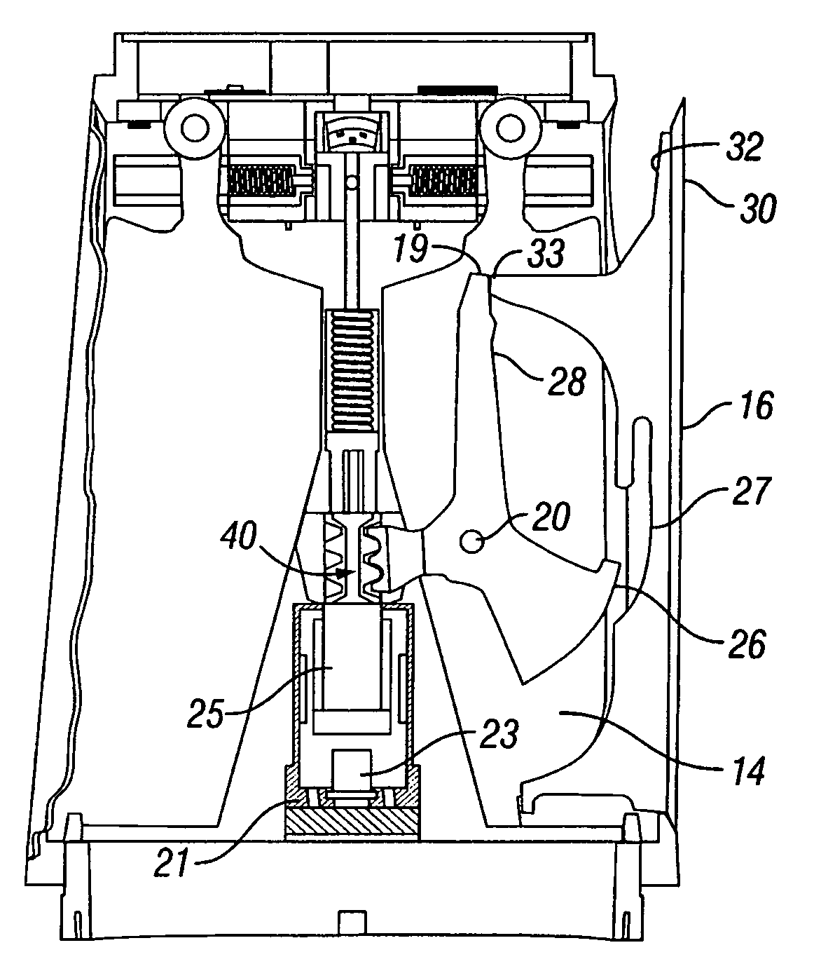
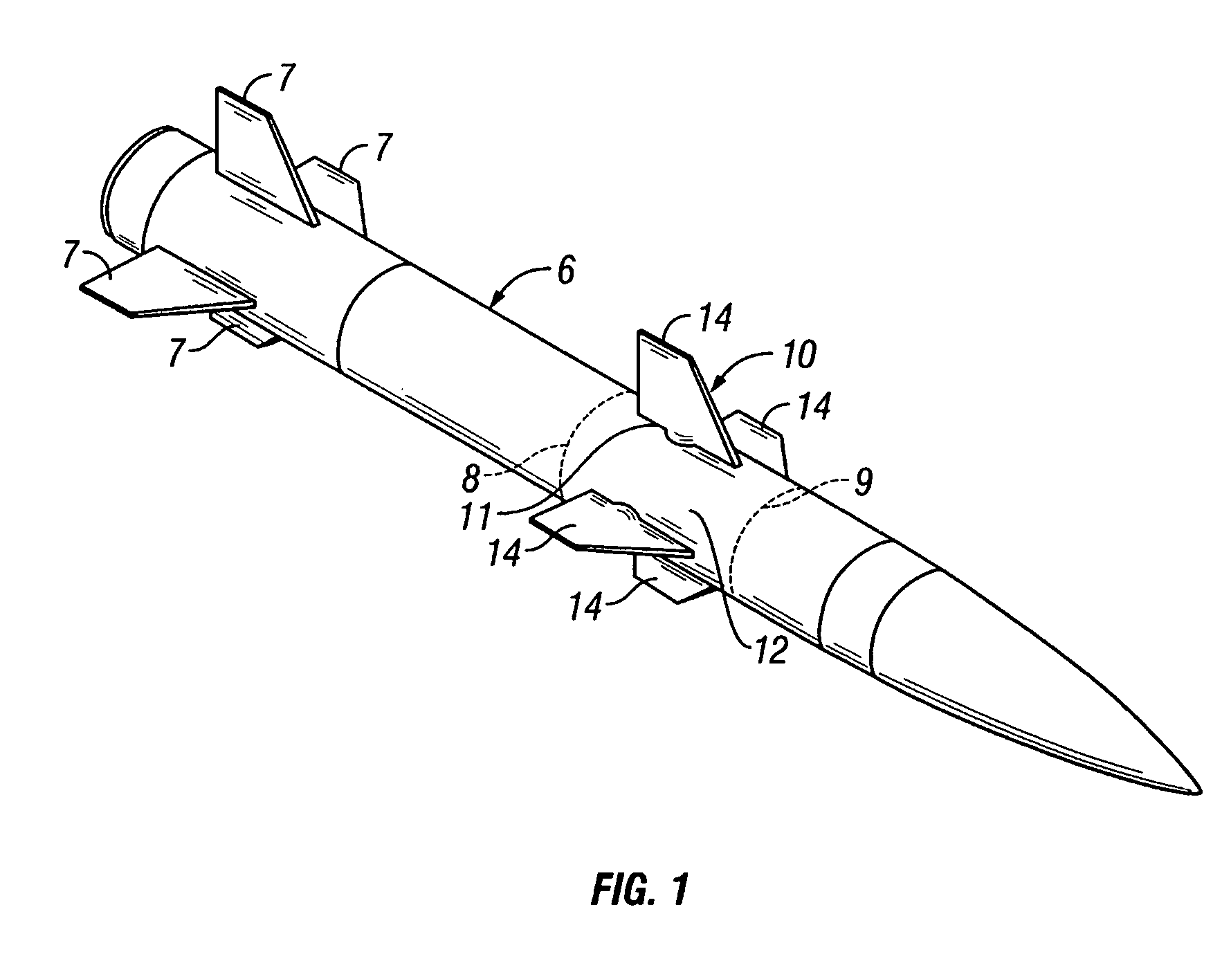
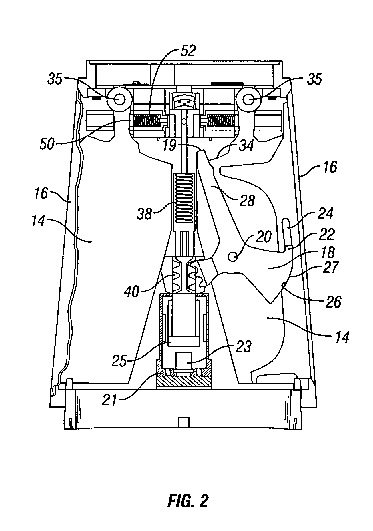
[0030]As shown in the drawings, particularly referring to FIG. 2, the actuator 10 is shown as it would be installed in a section of a missile 12 with a pair of fins, or canards, 14 in the stowed position. The actuator apparatus 10 is usually comprised of four fins, but alternatively two or three fins could be used. FIG. 2 shows the condition of the actuator 10 during gun launch and the initial portion of the flight. A pair of covers 16, one for each fin, are installed over the slots through which the fins deploy. However, only one cover is shown in FIG. 2 with its associated link, or latch arm, 18. The cover and latch arm on the left-hand side of FIG. 2 have been omitted to show details of the corresponding fin 14.

[0031]These covers 16 provide aerodynamic fairing and also seal the actuator assembly during long-term storage. They are held tightly closed against a gasket (not visible) during long-term storage and maintain a tight enough seal during the launch phase and flight phase to...

second preferred embodiment

[0041]The alternative embodiment of FIGS. 9 and 10 shows the actuator system 10′ with an electric motor 60 in place of the pyrotechnic device and piston of the embodiment of FIGS. 2–8. The motor 60 has a threaded shaft 62 which couples to the rack and sector gear 40, mating with an internally threaded portion thereof. Thus, as the motor 60 rotates the screw shaft 62, the gear mechanism 40 rotates the latch arms 18 in the manner described in the first embodiment.

[0042]Use of the electric motor 60 in the embodiment of FIGS. 9 and 10 provides a number of benefits, among which is the ability to reset and reuse the motor / actuator mechanism, thus making it easier to test the system prior to actual use. The electric motor drive also makes it possible to limit and control deployment velocity of the fins similar to the velocity damper on the pyrotechnic device as described above for the first embodiment. This is achieved through design of the motor with a limit on shaft RPMs and / or control o...


PUM


Abstract

A fin cover release and deployment system designed for high G forces of gun-launched missiles. In one embodiment, a pyrotechnic actuator drives actuator arms to first release and eject the fin slot covers, followed by deployment of the fins radially outward to the steering position. Following complete ejection of the covers, the fins are driven outwardly by cam surfaces along the latch arms, followed by a spring and wedge mechanism installed interiorly of the fin steering shaft to lock the fins in the fully deployed state. In another embodiment, a motor and rotating threaded shaft replace the pyrotechnic actuator.

Description

BACKGROUND OF THE INVENTION[0001]1. Field of the Invention[0002]The present invention generally relates to a system for latching the fin covers of a missile having retractable folding fins in the stowed position and for releasing and jettisoning the covers to permit deployment of the fins upon command following launch of the missile.[0003]2. Description of the Related Art[0004]Presently existing mechanisms for fin deployment on gun-launched projectiles are both complex and expensive. The requirement to withstand the acceleration forces, which typically range from 10,000 to 30,000 G's, places very stringent demands on the mechanisms. Therefore, the designs are required to be extremely robust in order to withstand the loads induced by these accelerations. It is a purpose of this invention to show a simple but unique configuration that is both low cost to produce and extremely robust. It is particularly capable of withstanding extreme accelerations.[0005]Presently, existing actuators f...

Claims


Application Information

Patent Timeline
Patent Type & Authority Patents(United States)
IPC IPC(8): F42B10/00F42B10/64F42B10/14
CPCF42B10/64F42B10/14
Inventor PERRY, CRAIGSCHROEDER, RICHARD W.VOIGT, ALLAN A.
Owner GEN DYNAMICS ORDNANCE & TACTICAL SYST
Learn More