
Sensor with suction cup array mount

a technology of array mount and sensor, which is applied in the direction of optical radiation measurement, instruments, investigating crystals, etc., can solve the problems of color distortion or damage to the lcd, surface must be undisturbed after measurement, and non-trivial problems, and achieve the effect of enabling positional stability of the sensor

Active Publication Date: 2005-04-19
X RITE SWITZERLAND +1
View PDF23 Cites 15 Cited by
  • Summary
  • Abstract
  • Description
  • Claims
  • Application Information

AI Technical Summary

Benefits of technology

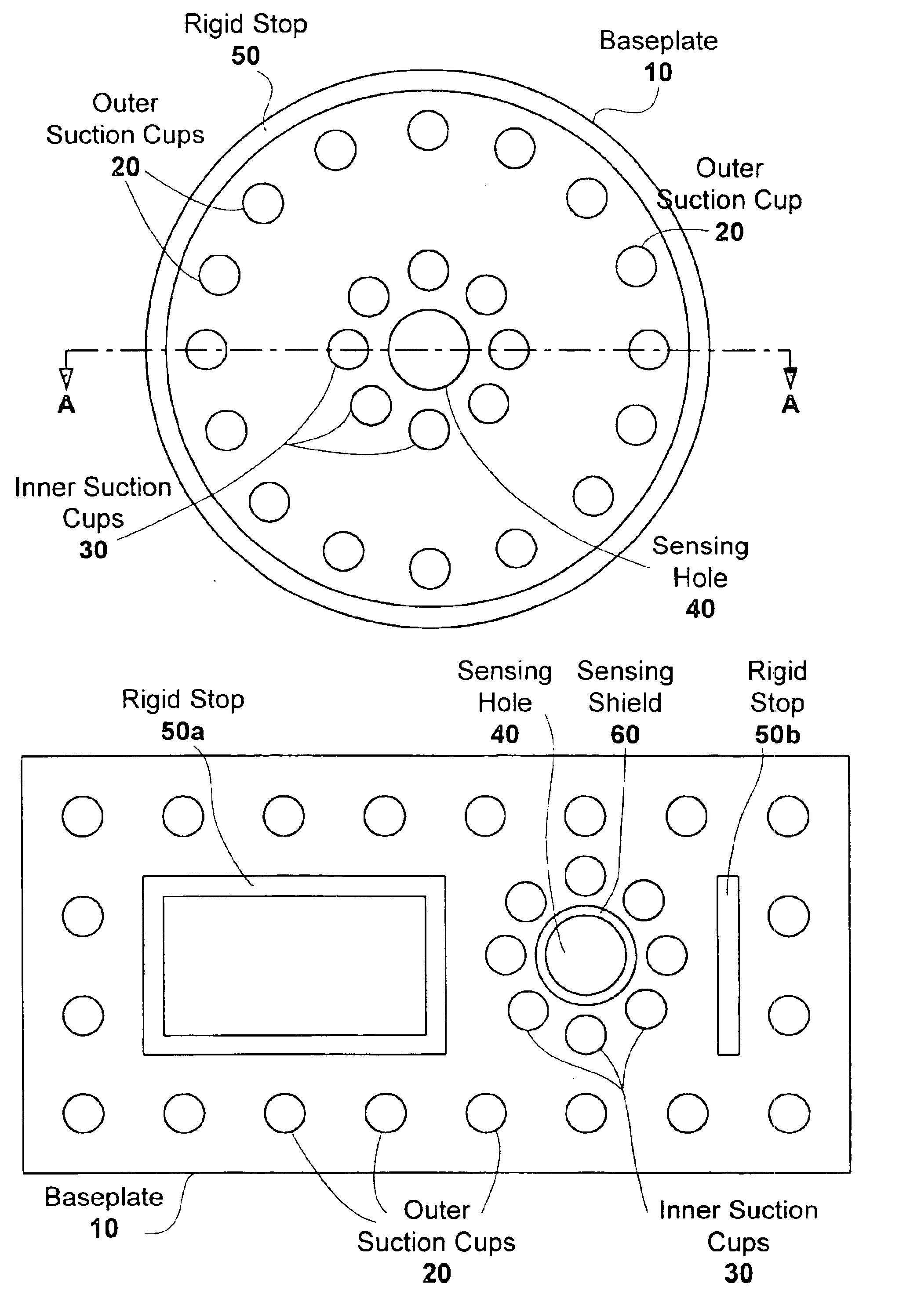
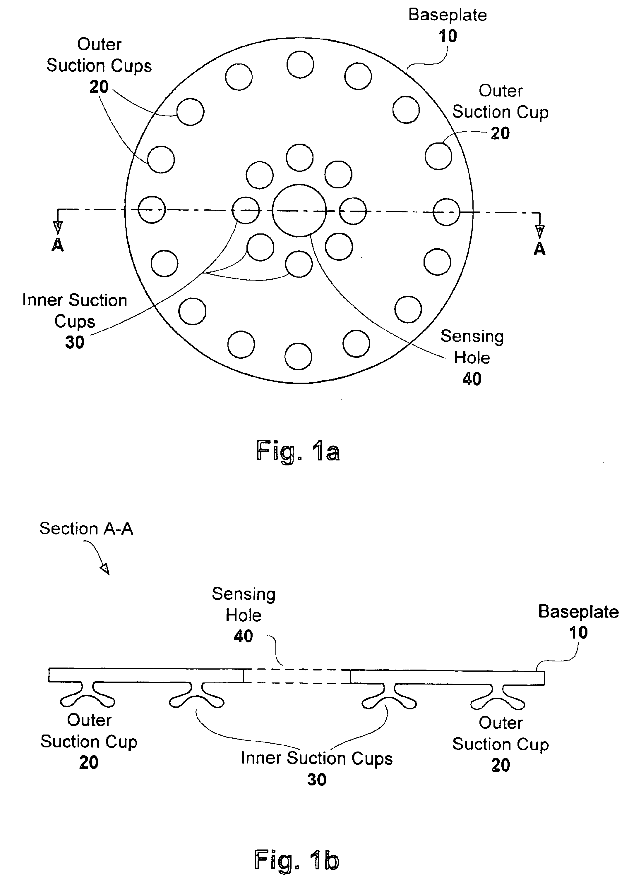
[0010]One embodiment of the present invention provides a mounting system for attaching a sensor (such as a colorimeter) to a target screen. The system includes an array of suction cups adapted to hold the sensor in position on the target screen. Each cup in the array has a maximum displacement distance of 0.115 inches or less, thereby enabling positional stability of the sensor. The maximum displacement distance defines a distance any one cup will move in transitioning from a fully engaged-state to a fully relaxed-state. A baseplate is operatively coupled to the array of suction cups, wherein the baseplate is adapted to be operatively coupled to a housing of the sensor or is part of the sensor housing. The array of suction cups can be, for example, a single piece of injection moldable elastomer or rubber. Also, the array can be integral with the baseplate, or can alternatively be bonded to the baseplate.
[0014]In one such embodiment, the array includes one or more rigid stops that operate to establish the pre-set distance of the calorimeter to the target screen. Each stop has a height that allows each of the suction cups to be fully seated. Each cup in the array can have, for example, a maximum displacement distance of 0.115 inches or less, thereby enabling positional stability of the colorimeter. In addition, each suction cup can have, for instance, a maximum cup diameter of 0.250 inches or less. The system may further include a baseplate that is operatively coupled to the array of suction cups, wherein the baseplate is adapted to be operatively coupled to a housing of the colorimeter or is part of the colorimeter housing. In one such embodiment, the baseplate is rigid and the system further includes a pull tab operatively coupled to one end of the baseplate and a pivot point at an opposite end, thereby allowing the mounting system to be cantilevered off of the target screen during removal.
[0015]Another embodiment of the present invention provides a mounting system for attaching a device to a target surface. The system includes an array of suction cups adapted to hold the device in position on the target surface, each cup in the array having a maximum displacement distance of 0.115 inches or less, thereby enabling positional stability of the device. The system further includes one or more rigid stops that operate to establish a pre-set distance of the device to the target surface, with each stop having a height that allows each of the suction cups to be fully seated. Each suction cup can have, for example, a maximum cup diameter of 0.250 inches or less.
[0017]The system may further include a baseplate that is operatively coupled to the array of suction cups, wherein the baseplate is adapted to be operatively coupled to a housing of the device or is part of the device housing. In one such case, the baseplate is rigid and the system further includes a pull tab operatively coupled to one end of the baseplate and a pivot point at an opposite end, thereby allowing the mounting system to be cantilevered off of the target surface during removal.

Problems solved by technology

For many cases, however, the surface must be undisturbed after measurement.
In more detail, the physical factors relating to mounting a calorimeter to a target device present a number of non-trivial problems.
Otherwise, color distortion or damage to the LCD will occur.
Also, LCD screens are particularly sensitive to the distribution and magnitude of the mounting forces.
However, such designs are cumbersome to use due to the nature of the strap or hanging apparatus, and generally provide a significant impediment to simple user operation.
Moreover, such designs may not operate to maximize the SNR of the colorimeter device, particularly those designs where the colorimeter's peripheral field of view is not limited.
These suction cup methods each suffer from reliability issues.
For example, if the seal fails due to an imperfection in materials or a particle of dust or debris, then air will leak into the cavity causing that suction cup to fail.
With the four corner type design, the weight of the device will be unevenly distributed, thereby causing a shift in alignment of the device and / or the failure of the remaining seals.
This problem is further exacerbated in that displays have a tendency to attract dust.
Moreover, the suction cups used in such designs have a relatively large depth.
As a result, a slow air leak will cause the distance between the screen and sensor to substantially increase, thereby adversely affecting device measurement accuracy.

Method used


Image

  • Sensor with suction cup array mount
  • Sensor with suction cup array mount
  • Sensor with suction cup array mount

Examples


Embodiment Construction

[0031]Embodiments of the present invention provide a mounting system for screen mounted calorimeters capable of measurement of emitted light from sources that are static (e.g., LCD displays, illuminated printed or graphic matter) and / or temporally active (e.g., CRT displays or strobed printed and graphic matter). The mounting system minimizes or otherwise removes factors that contribute to undesirable results, including changes in the mounting distance (calorimeter body to screen) over time. In addition, the mounting system enables the distribution of mount forces so as to not distort the screen output in the mount area or damage the screen, as well as to afford ease of removal of the calorimeter from the screen.

[0032]Positional stability of mounting system is achieved by using an array of pliable, small suction cups. Each suction cup has a shallow bowl to facilitate a short displacement distance and positional stability of the mount. The overall array enables distribution of the mo...


PUM

PropertyMeasurementUnit
diameteraaaaaaaaaa
displacement distanceaaaaaaaaaa
displacementaaaaaaaaaa

Abstract

A sensor mounting system having a suction cup array is disclosed. In one application, the system eases the initial positioning of the calorimeter on the screen to be measured, minimizes the force applied to the screen upon which it is mounted, and minimizes the distortion in the mounted area of the screen surface. In addition, the mounting system can be configured so that the distance from the colorimeter sensor to the screen will not significantly change over time. Such positional stability operates to improve SNR. The mounting system is further adapted for ease of removal from the screen upon which it is mounted. Applications not only include a mount for low to high accuracy calorimeters, but also for other measurement devices that can benefit from advantages of the present invention. Injection molding manufacturing techniques can be employed in fabrication of the system.

Description

RELATED APPLICATIONS[0001]This application claims the benefit of U.S. Provisional Application Nos. 60 / 418,308, filed 15 Oct. 2002, and 60 / 444,256, filed 3 Feb. 2003. Each of these applications is herein incorporated in its entirety by reference. In addition, this application is related to U.S. application Ser. No. 10 / 684,864, filed Oct. 14, 2003, titled “Colorimeter with High SNR” and to U.S. application Ser. No. 10 / 684,854, filed Oct. 14, 2003, titled “Colorimeter with Single Cable Low Impact Mounting System”. Each of these applications is herein incorporated in its entirety by reference.FIELD OF THE INVENTION[0002]The invention relates to techniques for mounting sensors to surfaces, and more particularly, to a colorimeter configured with a suction cup array mount.BACKGROUND OF THE INVENTION[0003]Measurement instrumentation often involves the mounting of a sensor to a surface to be measured. The parameters to be measured vary with the field of interest and sensing transducer employ...

Claims


Application Information

Patent Timeline
Patent Type & Authority Patents(United States)
IPC IPC(8): A45D42/00A45D42/14F16B47/00G01JG01N21/01G01N21/25G01N21/84
CPCG01N21/01G01J3/0291G01N2201/0646G01N2021/8477G01N2201/021G01N21/251
Inventor LUTZ, CARL DAVID
Owner X RITE SWITZERLAND
Learn More