
Universal tool holder

Active Publication Date: 2005-04-19
KAHN PETER P
View PDF25 Cites 65 Cited by
  • Summary
  • Abstract
  • Description
  • Claims
  • Application Information

AI Technical Summary

Benefits of technology

[0007]Accordingly, it is an object of the present invention to provide a universal tool holder which can be removably attached to most any tool.
[0009]It is also an object of the present invention to provide a universal tool holder which can be easily and quickly introduced into a retaining receiver.
[0012]It is a further object of the present invention to provide a retaining receiver for a universal tool holder which can be incorporated into an expandable mounting implement that can be removably secured to the hollow rung of a ladder.
[0014]It is also another object of the present invention to provide a universal tool holder and receiving retainer which is inexpensive to manufacture and easy to use.

Problems solved by technology

Although useful to some extent, such tool belts present inherent deficiencies which limit their usefulness.
For example because cloth is not necessarily a rigid structure, cloth loops may close when not in use, making it difficult for the user to replace the tool into the loop with one hand.
More over, a loop may tightly constrict about the tool handle as the tool settles into position, thereby making it difficult to remove the tool when needed.
Similar problems arise with the use of the more rigid leather loops.
While these tool-toting devices have achieved commercial success, a disadvantage to these devices is that they cannot be removably secured to all types of tools.
In addition, these tool-toting devices are not adapted easily for suspension from a wall, ladder or other object.
However, none of the clamping members described in these patents are capable of securely engaging a tool and suspending the thus-engaged tool from a ladder.

Method used


Image

  • Universal tool holder
  • Universal tool holder
  • Universal tool holder

Examples


Embodiment Construction

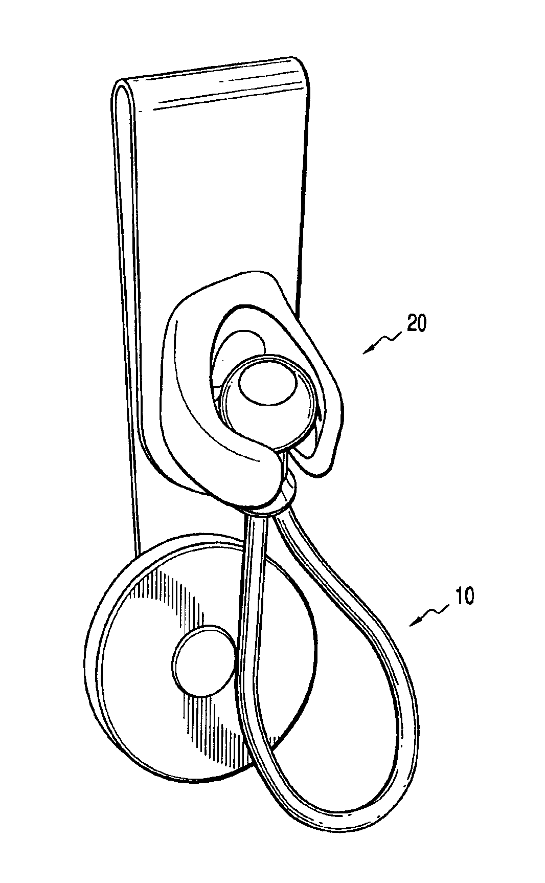
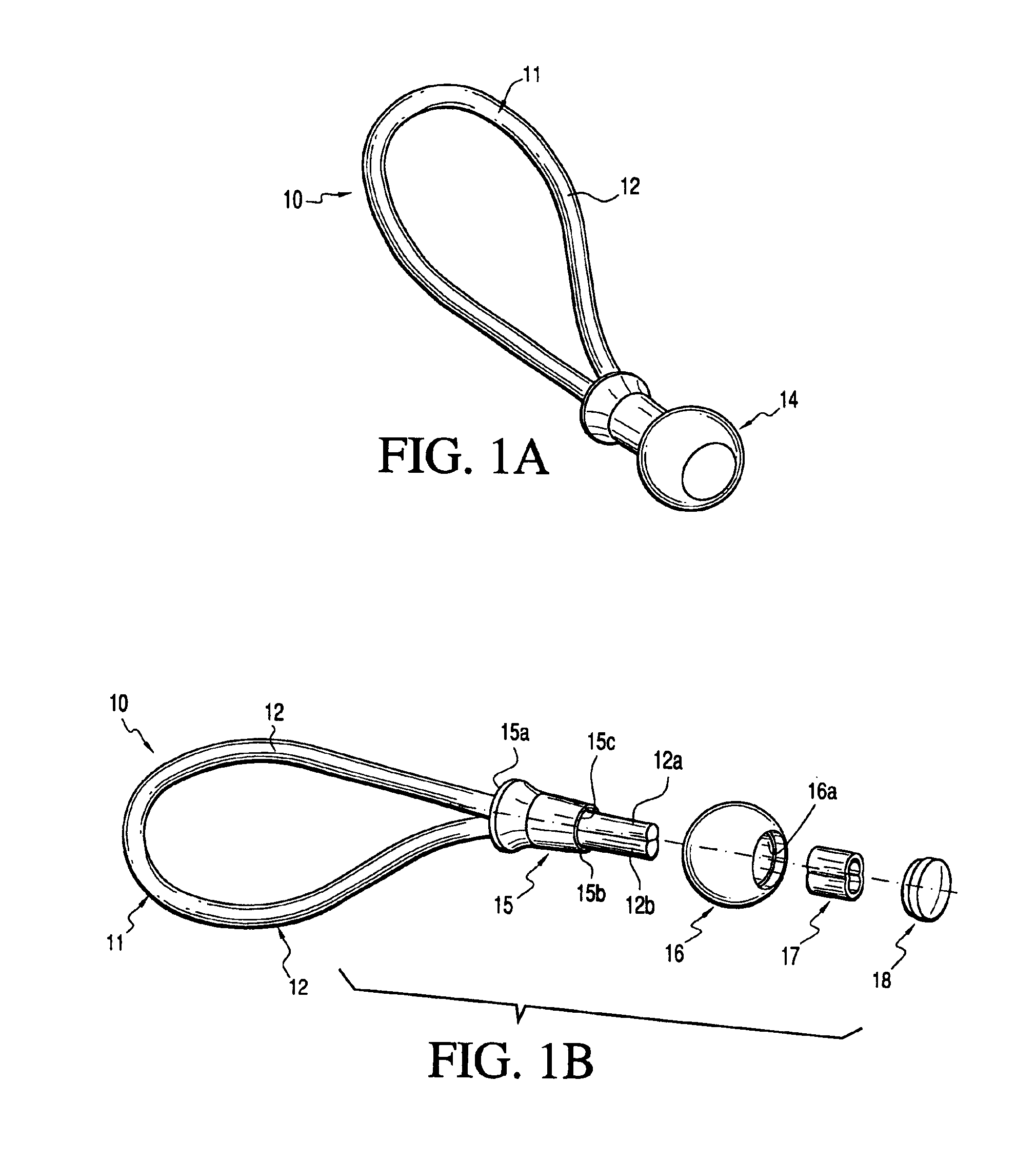
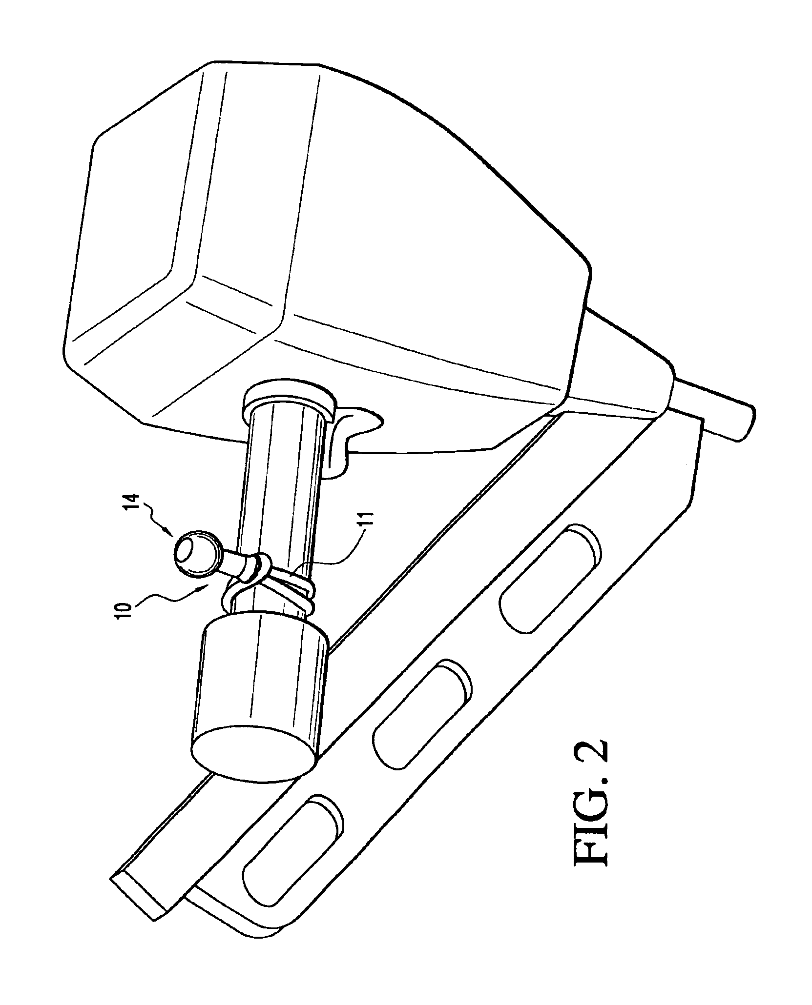
[0029]The present invention relates to a universal tool holder which can be attached to most any type of tool and which can be removably secured, through the utilization of a unique retaining receiver, to a belt clip or a mounting implement for attachment to a wall, ladder or other article. Referring now to FIGS. 1A and 1B, the universal tool holder 10 comprises a looped end 11 formed from a stretchable cord 12, such as a bungee cord, having a first end 12a and a second end 12b, and a ball end 14. The universal tool holder further comprises a frusto-conical locking spacer 15 having a proximal end 15a, a distal end 15b and a central opening 15c, a spherical element 16, hereinafter referred to as a ball, having an aperture 16a extending therethrough, said aperture having a diameter corresponding to the outer diameter of said distal end 15b of said locking spacer 15, a crimped locking element 17 and a cap 18.

[0030]The looped end 11 is constructed by introducing both first end 12a and s...


PUM


Abstract

A universal tool holder for carrying a tool or other article, for example, a cordless drill, nail gun, hammer or shovel is provided comprising a stretchable cord that is formed into a looped end and adapted to be wrapped about the handle of a tool in such a manner that it tightly engages the tool, and a second end having a retainable object, such as a ball, that is configured to be safely and securely held within a retaining receiver. The retaining receiver is in the form of a socket-type receiver configured to correspond to the geometrical shape of the retainable object such it can removably secure the retainable object. The socket-shaped retaining receiver can be incorporated into a variety of articles usefull in carrying and storing tools, including a belt clip, a wall mounting implement or a ladder mounting implement. By integrating the retaining receiver into such a variety of articles, any tool carried by the universal tool holder can be removably secured to the retaining receiver, thereby enabling a user to suspend the tool from a belt clip, ladder or wall.

Description

FIELD OF INVENTION[0001]The present invention relates to the field of devices for carrying a tool, such as a cordless drill, nail gun, hammer or any other tool having a handle. More particularly, the present invention relates to a universal tool holder adapted to be secured to most any tool and which also can be removably secured to a belt clip or a ladder. More specifically, the present invention relates to a universal tool holder comprising a stretchable cord that is formed into a looped end and adapted to be wrapped about the handle of a tool in such a manner that it tightly engages the tool, and a ball end that is adapted to be safely and securely held within a retaining receiver. The retaining receiver can be integrated into a belt clip or a mounting implement to engage a wall, ladder or other article, thereby enabling the tool holder to be suspended from a belt clip or ladder.BACKGROUND OF THE INVENTION[0002]Devices for carrying tools are well known in the prior art. Many such...

Claims


Application Information

Patent Timeline
IPC IPC(8): F16B45/00A45F5/02A47F5/00B25H3/00E06C7/14
CPCA45F5/02B25H3/00E06C7/143F16B45/00A47F5/0006A45F5/021A45F2200/0575Y10T24/39
Inventor KAHN, PETER P.
Owner KAHN PETER P
Learn More