Quick change power tool chuck

Inactive Publication Date: 2005-04-19
DEROSA JOHN L +1
View PDF17 Cites 35 Cited by
  • Summary
  • Abstract
  • Description
  • Claims
  • Application Information

AI Technical Summary

Benefits of technology

[0008]An object of the present invention is to provide a chuck having greatly increased holding torque, without relying on set screws, flats, k

Problems solved by technology

Although there are a number of existing chucks and like devices for retaining cutting bits in power tools and driven spindles, they all have some disadvantages which detract from their advantages.
For example, while some chucks hold the cutting bit with enough force that slippage will not occur, the changing of the bit can be very cumbersome and time consuming.
Others allow an easy changing of bits but do not provide enough holding torque to prevent slippage from occurring.
However, at the present time, there are no chucks currently available which allow an easy change of the cutting bit and which also provide the increase in mechanical advantage necessary to enable a large enough force to be exerted on the cutting bit so as to substantially increase the holding torque.
Accordingly, if the chuck is relatively heavy and bulky in size as in the case of the chuck of the Walsh patent, unwanted and sometimes severe vibration can oc

Method used


Image

  • Quick change power tool chuck
  • Quick change power tool chuck
  • Quick change power tool chuck

Examples


Embodiment Construction

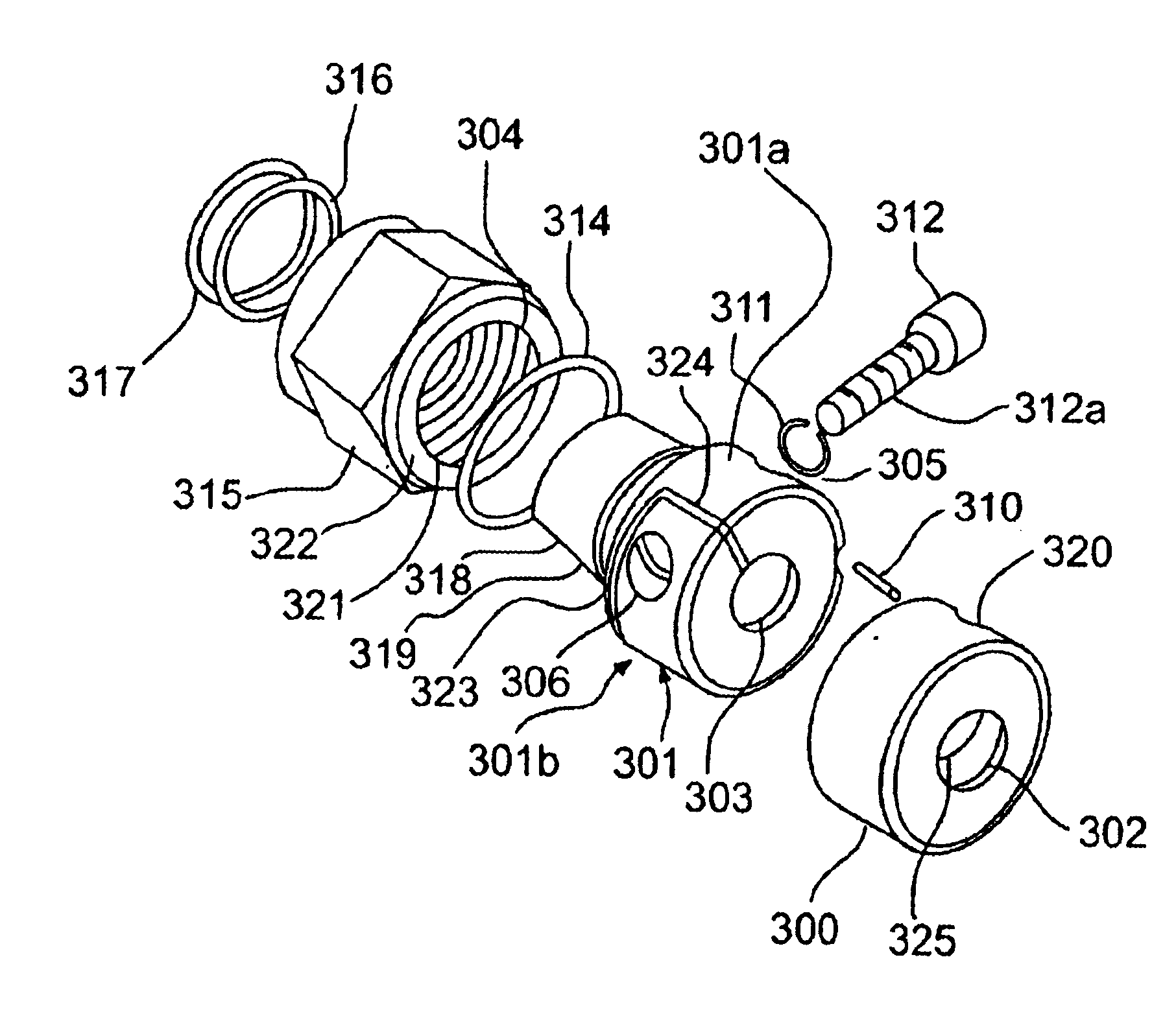
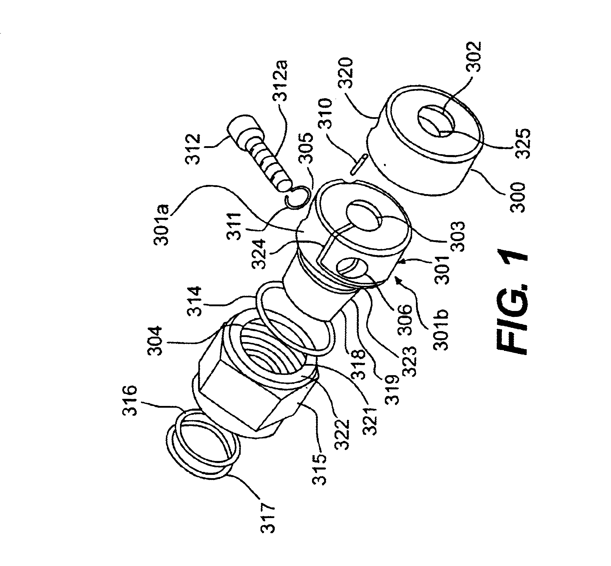
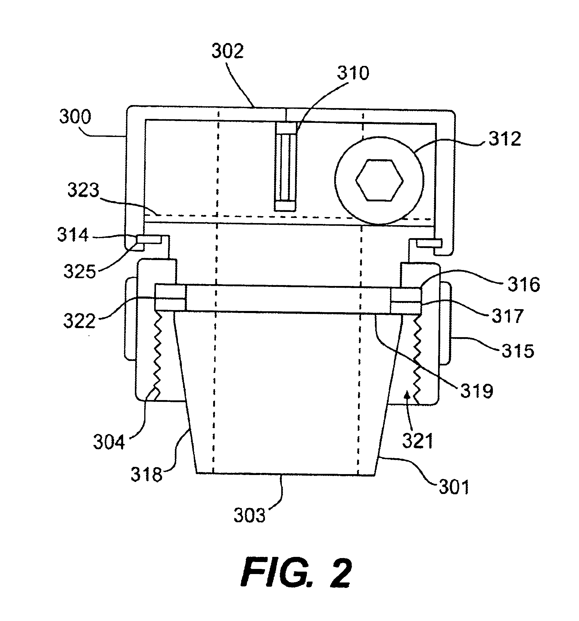
[0027]FIG. 1 shows an exploded perspective view of a preferred embodiment of the chuck device of the invention while FIGS. 2, 3(a) and 3(b) show various features of this embodiment. The chuck device is composed of nine parts as shown in FIG. 1, viz., a safety cover 300, a main body 301, a pin 310, a washer 311, a cap screw 312, a lock ring 314, a nut 315, and two further lock rings 316 and 317.

[0028]In accordance with a key feature of the invention, the main body 301 is adapted to be mechanically deformed by the incorporation thereof of two slots 323 and 324 that extend perpendicular to each other. These slots are perhaps best seen in FIG. 3(b) and, as shown, divide an annular end portion of main body 301 into a fixed part or side 301a and a movable part or side 301b. As illustrated in FIG. 3(a), slot 323 extends inwardly from the circumferentially extending side surface of main body 301 so as to terminate in the main body 301 along a line (indicated by the dashed line 323) a portio...


PUM


Abstract

An improved quick change power tool chuck is provided which is principally used on a wood working router but could also be used in many other power tool applications. The key features of the quick change chuck are the unique way that it secures the cutting bit from unwanted slippage, the large mechanical advantage thereof and the speed in which a cutting bit can be removed and replaced. The chuck can be aligned and attached to the power tool in the same manner that a standard collet is aligned and attached to the router spindle.

Description

CROSS-REFERENCE TO RELATED APPLICATIONS[0001]This application claims benefit of the filing date of Provisional Patent Application No. 60 / 432,638, filed on Dec. 12, 2002.BACKGROUND OF THE INVENTION[0002]1. Field of the Invention[0003]The present invention relates to quick change chucks for power tools and, more particularly, to an improved chuck that provides increased holding force without sacrificing ease of bit changing.[0004]2. Discussion of Related Art[0005]Although there are a number of existing chucks and like devices for retaining cutting bits in power tools and driven spindles, they all have some disadvantages which detract from their advantages. For example, while some chucks hold the cutting bit with enough force that slippage will not occur, the changing of the bit can be very cumbersome and time consuming. Others allow an easy changing of bits but do not provide enough holding torque to prevent slippage from occurring. There are a few chucks that allow easy changing of b...

Claims


Application Information

Patent Timeline
IPC IPC(8): B23B31/10B23B31/20B23B31/103
CPCB23B31/103B23B31/202Y10T279/17316Y10T279/17393Y10T279/17675B23B2231/2097B23B31/2025
Inventor DEROSA, JOHN L.
Owner DEROSA JOHN L
Why Eureka
Try Eureka