Needle assembly

a technology of needles and parts, applied in the field of needle protection devices, can solve the problems of improper shielding completion, user failure to perform manual shielding operation properly or completely,

Inactive Publication Date: 2005-04-19
BECTON DICKINSON & CO
View PDF6 Cites 22 Cited by
  • Summary
  • Abstract
  • Description
  • Claims
  • Application Information

AI Technical Summary

Benefits of technology

[0019]Upon completion of the medical procedure, the needle cannula is withdrawn from the patient and the wings are rotated down and toward one another. This rotational movement of the first and second wings down and toward one another moves the slot of the center sleeve into alignment with the projection on the hub. As a result, the spring biases the hub proximally and causes the projection of the hub to move proximally through the slot of the center sleeve and into the slot of the proximal sleeve. This proximal movement of the hub by the spring causes the needle cannula to be retracted safely within the sleeves of the first and second wings. The spring maintains its biasing force to keep the needle cannula in the safely shielded position. Additionally, further downward rotation of the wings may move the slot of the center sleeve beyond the projection of the hub. Thus, the center sleeve retains the projection in the slot of the proximal sleeve and holds the needle cannula in the shielded position.

Problems solved by technology

Shielding may not be completed properly if the user forgets to perform the two-handed shielding operation or if the exigencies of the medical situation prevent the user from performing the two-handed shielding operation.
Additionally, a potential exists that the user will not perform the manual shielding operation properly or completely.

Method used


Image

  • Needle assembly
  • Needle assembly
  • Needle assembly

Examples


Embodiment Construction

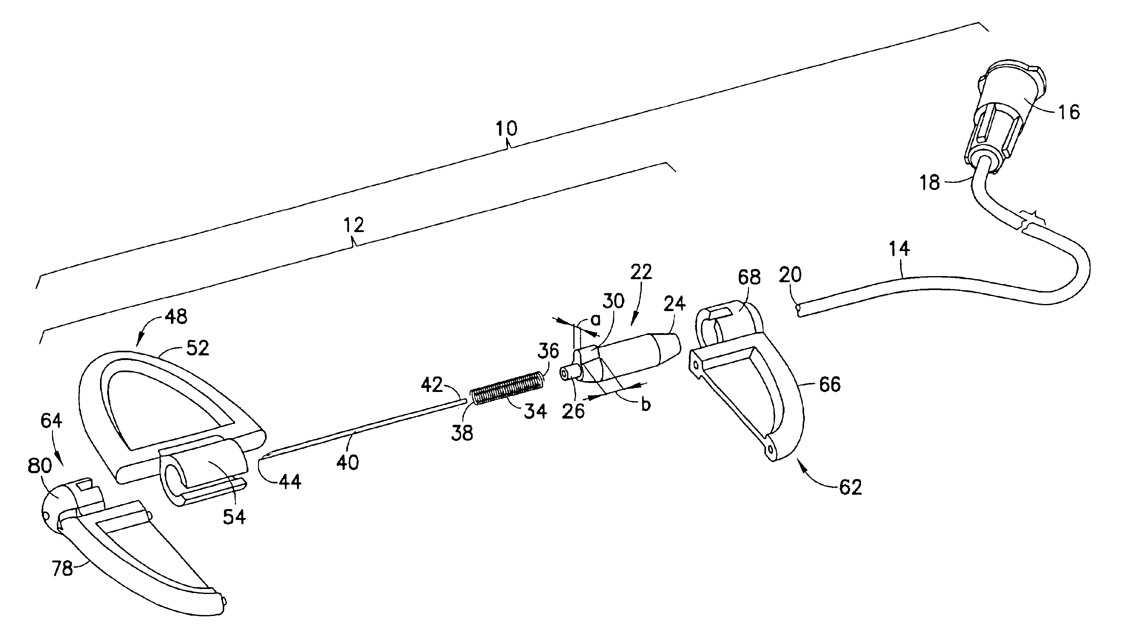
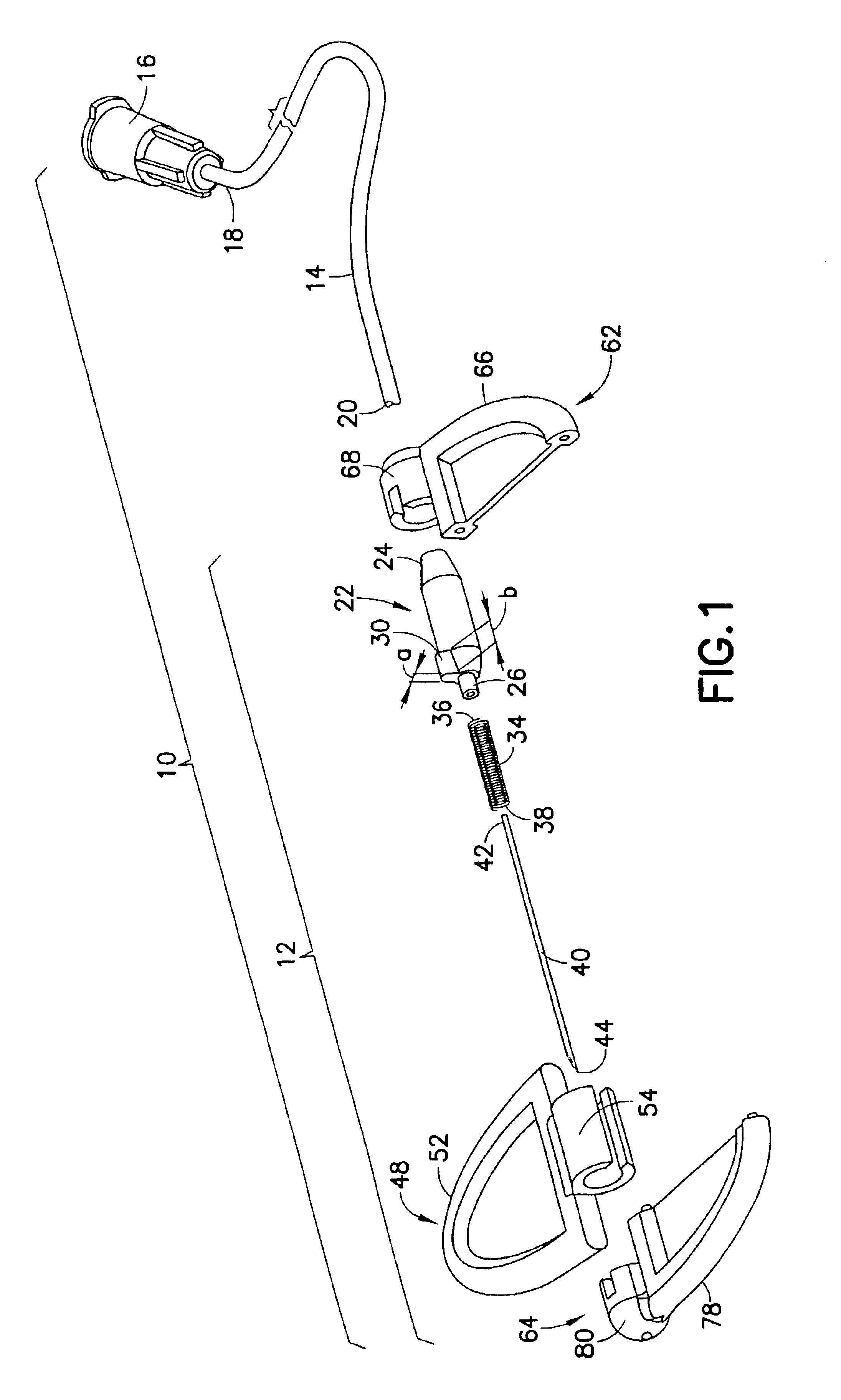
[0033]An IV infusion set or blood collection set in accordance with the subject invention is identified generally by the numeral 10 in FIGS. 1, 10 and 12, and for simplicity will be referred to herein as an IV infusion set. IV infusion set 10 includes a needle assembly 12, a length of flexible plastic tubing 14 and a fitting 16. Flexible tubing 14 includes a proximal end 18 and a distal end 20. Proximal end 18 of flexible plastic tubing 14 is secured to fitting 16. As illustrated herein, fitting 16 is a female luer fitting that communicates with the passage through tubing 14. However, other fittings may be employed, such as a non-patient needle assembly or a luer-activated device port.

[0034]Needle assembly 12 includes a hub 22 that is formed unitarily from a transparent plastic material, such as polypropylene. Hub 22 includes a proximal end 24, a distal end 26 and a passage 28 extending between the ends. Distal end 20 of tubing 14 is mounted securely to proximal end 24 of hub 22 so ...


PUM


Abstract

A shieldable winged needle assembly includes a hub and a cannula projecting distally beyond the hub. A spring is telescoped over the cannula and engages with or into distal portions of the hub. A hub guide projects radially out from the hub. A first wing includes a center sleeve rotationally mounted on the hub and axially movable along the hub when a slot formed in the center sleeve aligns with the hub guide. A second wing has proximal and distal sleeves mounted at opposite ends of the center sleeve. The proximal and distal sleeves each are rotationally mounted relative to the hub and each include slots that enable sliding movement of the hub guide when the slots of the second wing align with the slot of the first wing. The spring propels the cannula and hub into a shielding position when the slots of the wings are rotated into alignment with one another.

Description

RELATED APPLICATIONS[0001]This application claims priority on U.S. Provisional Patent Appl. No. 60 / 383,521 filed May 28, 2002.BACKGROUND OF THE INVENTION[0002]1. Field of the Invention[0003]The invention relates to needle protection devices, and particularly a safety device for use with an intravenous infusion needle.[0004]2. Description of the Related Art[0005]A device commonly referred to as a “butterfly” or winged intravenous infusion assembly often is used for IV infusions and / or for withdrawing venous blood. This device also may be known as a hemodialysis needle. The device typically includes a needle hub with opposite proximal and distal ends and a passage extending between the ends. The device also includes a needle cannula with a proximal end, a sharply pointed distal end and a lumen extending between the ends. The proximal end of the needle cannula is securely mounted in the hub of the device so that the lumen through the needle cannula communicates with the passage through...

Claims


Application Information

Patent Timeline
Patent Type & Authority Patents(United States)
IPC IPC(8): A61M25/06A61M5/158A61M5/14A61M5/32
CPCA61M5/158A61M25/0637A61M25/0631A61B5/153A61M5/3257A61M25/0612A61M5/3271A61B5/15003A61B5/150389A61B5/150519A61B5/150656A61B5/15074A61B5/1535
Inventor COLEMAN, JOHN D.BRESSLER, PETERDELISO, JORDANWILKINSON, BRADLEY M.TURPAULT, MATHIEU
Owner BECTON DICKINSON & CO
Why Eureka
Try Eureka