
Optical height zeroing device

a technology of laser beam and height zeroing, which is applied in the direction of instruments, wound drains, diagnostic recording/measuring, etc., can solve the problems of increasing pressure in the ventricles in the brain, difficult to ensure that the laser beam is horizontally level, and enlarge the ventricles

Inactive Publication Date: 2005-04-19
INTEGRA LIFESCI SWITZERLAND SARL
View PDF6 Cites 11 Cited by
  • Summary
  • Abstract
  • Description
  • Claims
  • Application Information

AI Technical Summary

Problems solved by technology

Blockage of the flow of CSF consequently creates an imbalance between the amount of CSF produced by the choroid plexus and the rate at which CSF is absorbed into the bloodstream, thereby increasing pressure within the ventricles in the brain, which causes the ventricles to enlarge.
While such laser devices have proven effective, it can be difficult to ensure that the laser beam is horizontally level.
Additional drawbacks of laser devices include the costs and need to power such devices, as well as any potential risks that may result from shining a laser beam directly at a patient.
Drawbacks of these devices include the need for the patient to be relatively close to the support member, as well as the possible risk of injuring a patient with the device while positioning the device adjacent the patient's zero reference point.
Such devices can also be awkward to handle, as they often require one person to hold the T- or L-square, while another person adjusts the height of the drainage system.
Moreover, T- and L-square devices are often very large, and require sizable storage spaces.

Method used


Image

  • Optical height zeroing device
  • Optical height zeroing device
  • Optical height zeroing device

Examples


Embodiment Construction

[0020]The present invention provides a leveling device for vertically aligning two objects positioned at a distance apart from one another. More particularly, a leveling device for use with an external drainage system is provided. The leveling device is effective to determine and set the zero pressure point on an external draining system with respect to a patient. The zero pressure point is the point at which the ICP is zero, and thus the pressure differential between the patient's cerebrospinal fluid system and an external drainage system is zero. Once the zero pressure point is determined, the ICP can be adjusted to accurately control the flow of fluid from the patient to the external drainage system.

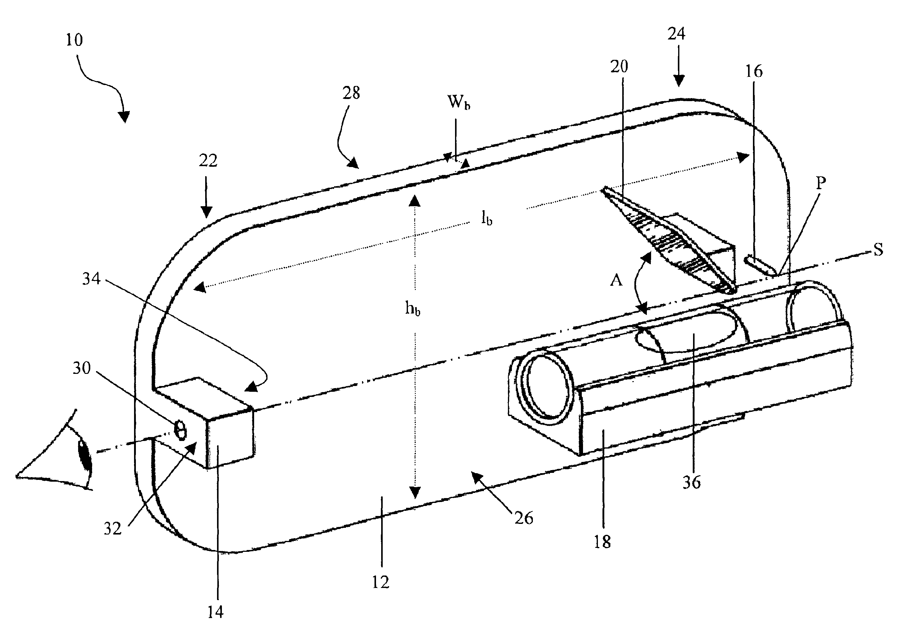
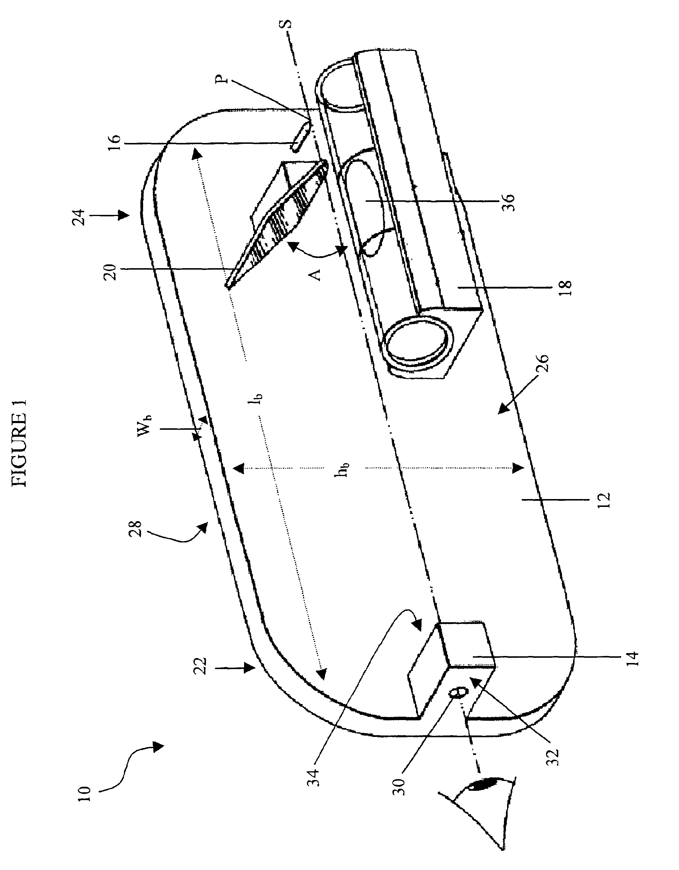
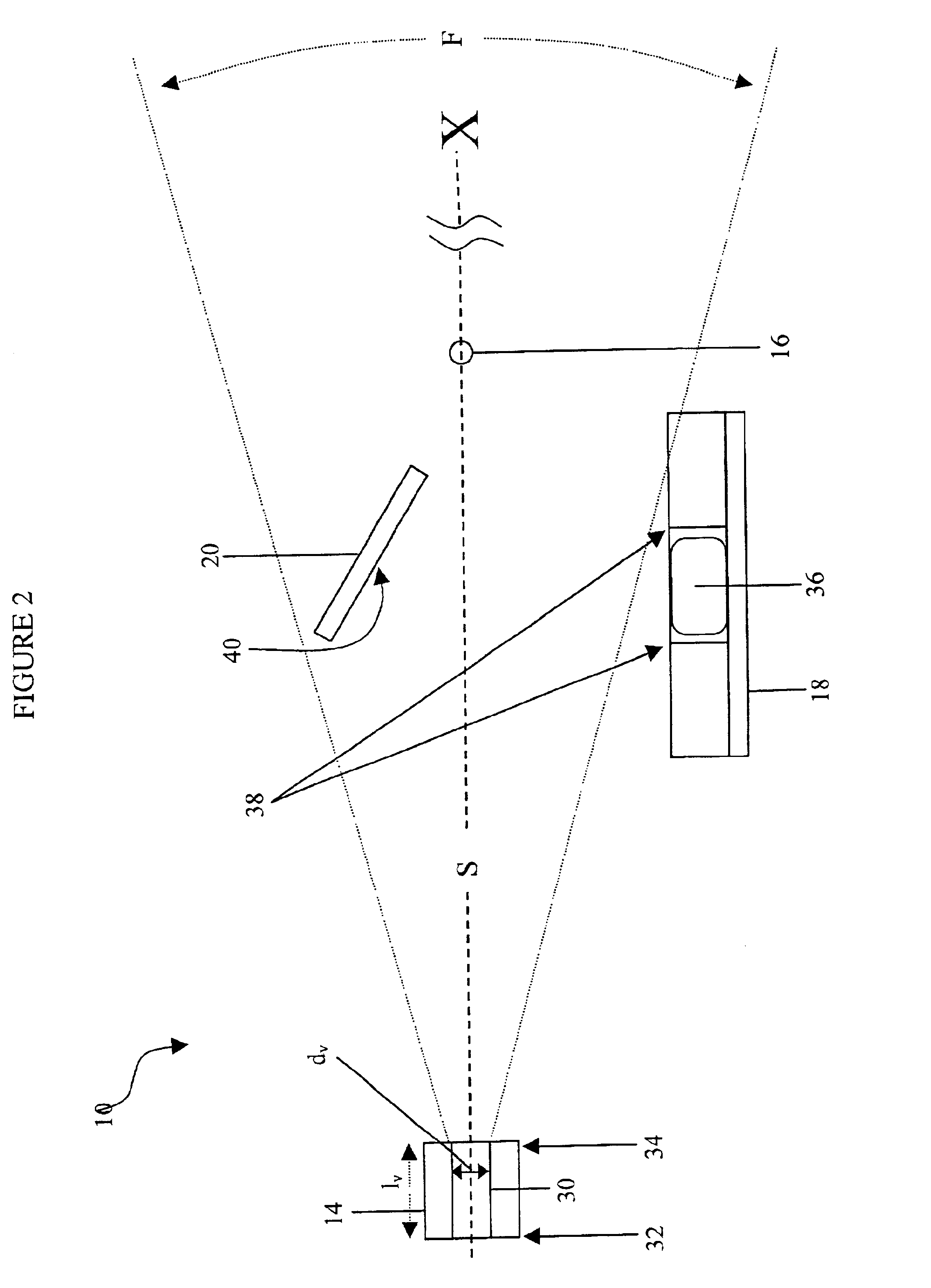
[0021]As shown in FIGS. 1 and 2, the device 10 generally includes a body 12 having a viewing element 14 defining a field of vision F, and a reference point indicator 16 spaced apart from the viewing element 14 and disposed within the field of vision F. The viewing element 14 and the r...


PUM


Abstract

A leveling device for determining the zero pressure point of an external draining system with respect to a patient is provided. The leveling device generally includes a body having a viewing element defining a field of vision, a reference point indicator spaced apart from the viewing element and disposed within the line of vision, which together define a line of sight, and a horizontal level indicator mated to the body and oriented parallel to the line of sight established by the viewing element and the reference point indicator. The horizontal level indicator indicates the horizontal alignment of the body with respect to a particular reference point viewed through the viewing element and indicated by the reference point indicator. The device optionally includes a reflector element adjacent to the horizontal level indicator within the field of vision, where the horizontal level indicator is visible through the viewing element via the reflector element.

Description

FIELD OF THE INVENTION[0001]The present invention relates to a device for controlling intracranial pressure, and in particular to a leveling device for determining the zero pressure point of an external draining system with respect to a patient.BACKGROUND OF THE INVENTION[0002]Cerebrospinal fluid (CSF) is a clear, colorless fluid that is primarily produced by the choroid plexus and surrounds the brain and spinal cord. CSF constantly circulates through the ventricular system of the brain and is ultimately absorbed into the bloodstream. CSF has three important functions. First, because CSF keeps the brain and spinal cord buoyant, it acts as a protective cushion or “shock absorber” to prevent injuries to the central nervous system. Second, CSF acts as the vehicle through which nutrients are delivered to the brain, and conversely, as the vehicle through which waste products are carried away from the brain tissue. Finally, by flowing between the cranium and the spine, CSF can compensate ...

Claims


Application Information

Patent Timeline
Patent Type & Authority Patents(United States)
IPC IPC(8): G01C5/00G01C5/04A61M1/00
CPCA61B5/031G01C5/04A61B5/061A61M2205/3348
Inventor WILSON, STEPHEN F.
Owner INTEGRA LIFESCI SWITZERLAND SARL
Learn More