Wiring harness arrangement assembly for sliding door of car

Inactive Publication Date: 2005-04-19
YAZAKI CORP
View PDF11 Cites 33 Cited by
  • Summary
  • Abstract
  • Description
  • Claims
  • Application Information

AI Technical Summary

Benefits of technology

[0036]Next, advantageous effects of the present invention will be discussed.
[0037]In the first aspect of the invention, the corrugated tube is secured to the pivotal harness guide, so that the wiring harness received in the corrugated tube 4 is turned together with the harness support 5. Thereby, the wiring harness and the corrugated tube 4 will not receive an abnormal torsional or bending force, eliminating a damage or an undesirable permanent deformation of the wiring harness and the corrugated tube 4 due to the repeated opening and closing of the sliding door. Furthermore, the corrugated tube 4 will not make a springback motion and will not interfere with the sliding door 6 and the car body 1, so that neither an undesirable noise nor a damage of the corrugated tube 4 due to the interference may happen.
[0038]The corrugated tube 4, which accommodates the wiring harness consisting of a plurality of electrical cables, eliminates a hand work to make a bundle of the cables with winding tapes. This improves the flexibility of the wiring harness. In this invention, the pivotal harness guide holds not the wiring harness but the corrugated tube, so that the wiring harness freely slides in the corrugated tube. Thus, the bending flexibility of the wiring harness remarkably improves as compared with when the wiring harness is directly held by the pivotal harness guide.
[0039]In the second aspect of the invention, the base member is secured to the body or the sliding door, and the harness support member is supported turnably around the connect

Problems solved by technology

Thus, repeated opening and closing operations of the sliding door 6 tend to disadvantageously cause a damage of the wiring harness and the corrugated tube 4 at the bent portions 4a and 4b.
Thereby, a damage of the wiring harness and the corrugated tube 4 may happen and an undesired noise may be generated.
Moreover, a torsional force may be exerted on the wiring harness and the corrugated tube 4 due to the forcible bent of the corrugated tube 4, causing a damage of the wirin

Method used


Image

  • Wiring harness arrangement assembly for sliding door of car
  • Wiring harness arrangement assembly for sliding door of car
  • Wiring harness arrangement assembly for sliding door of car

Examples


second embodiment

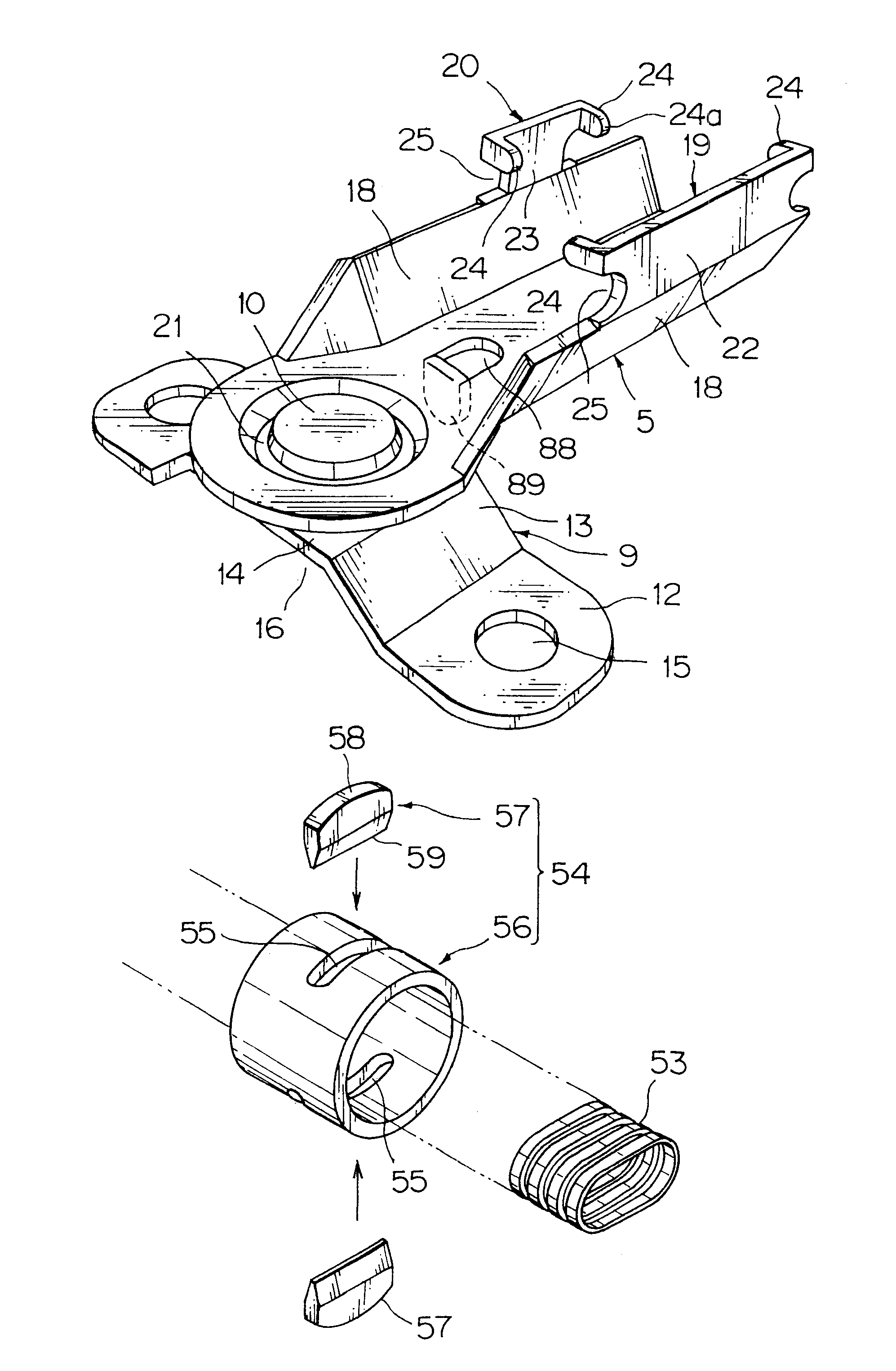
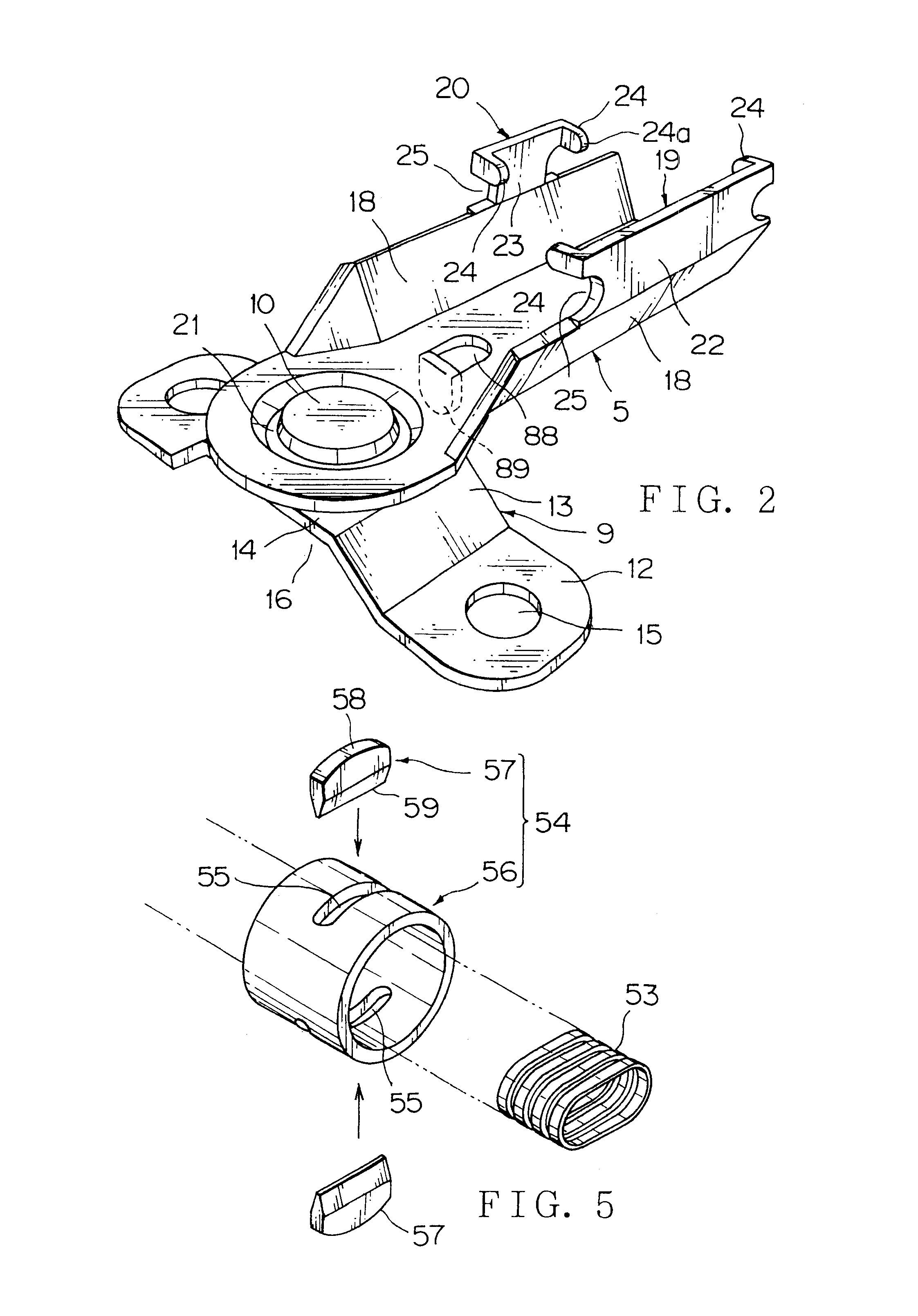
[0092]FIG. 4 shows a harness support member harness support 31 turnably supporting a harness guide.

[0093]The harness support 31 can be turnably supported by the base member 9 (FIG. 2) and the rivet 10 (FIG. 2) which are the same as those of the embodiment of FIG. 2. The same components will not be discussed again. In place of the base member 9, a bolt, a collar, and a nut may be used to turnably support the harness support 31. In that case, the harness support 31 is called as a pivotal harness guide. The harness support 31 may be secured to the car body 1 with a bolt such that the corrugated tube 4 is turnable in a circumferential direction. These modified examples may be applied to any of embodiments (FIGS. 6 and 7) described later.

[0094]The harness support 31 is divided into a lower cradle 32 and an upper cap 33 which are made of a synthetic resin material.

[0095]The cradle 32 has a horizontal short plate 34 formed with a fixing hole 35 for turnably supporting or securing it to the...

third embodiment

[0110]FIG. 6 shows a harness support member 61 turnably supporting a harness guide.

[0111]The harness support 61 has a laterally elongated harness guide portion 62 extended from the cradle 32 of the harness support 31, and the other construction is the same as the harness support 31 of FIG. 4, for which the same reference numerals as those of FIG. 4 are used. When the harness support 61 is directly turnably supported by the car body without a base member, the harness support 61 is called as a pivotal harness guide. The harness support 31 may be secured to the car body such that the corrugated tube is turnable in its circumferential direction to prevent an abnormal torsional deformation of the corrugated tube.

[0112]The harness guide portion 62 is extended horizontally from one of the walls 64 of the cradle 32. The harness guide portion 62 has a supporting plate 84, a short side wall 65 formed at each side of the supporting plate 84 for guiding the corrugated tube 4, a reduced-width se...

fourth embodiment

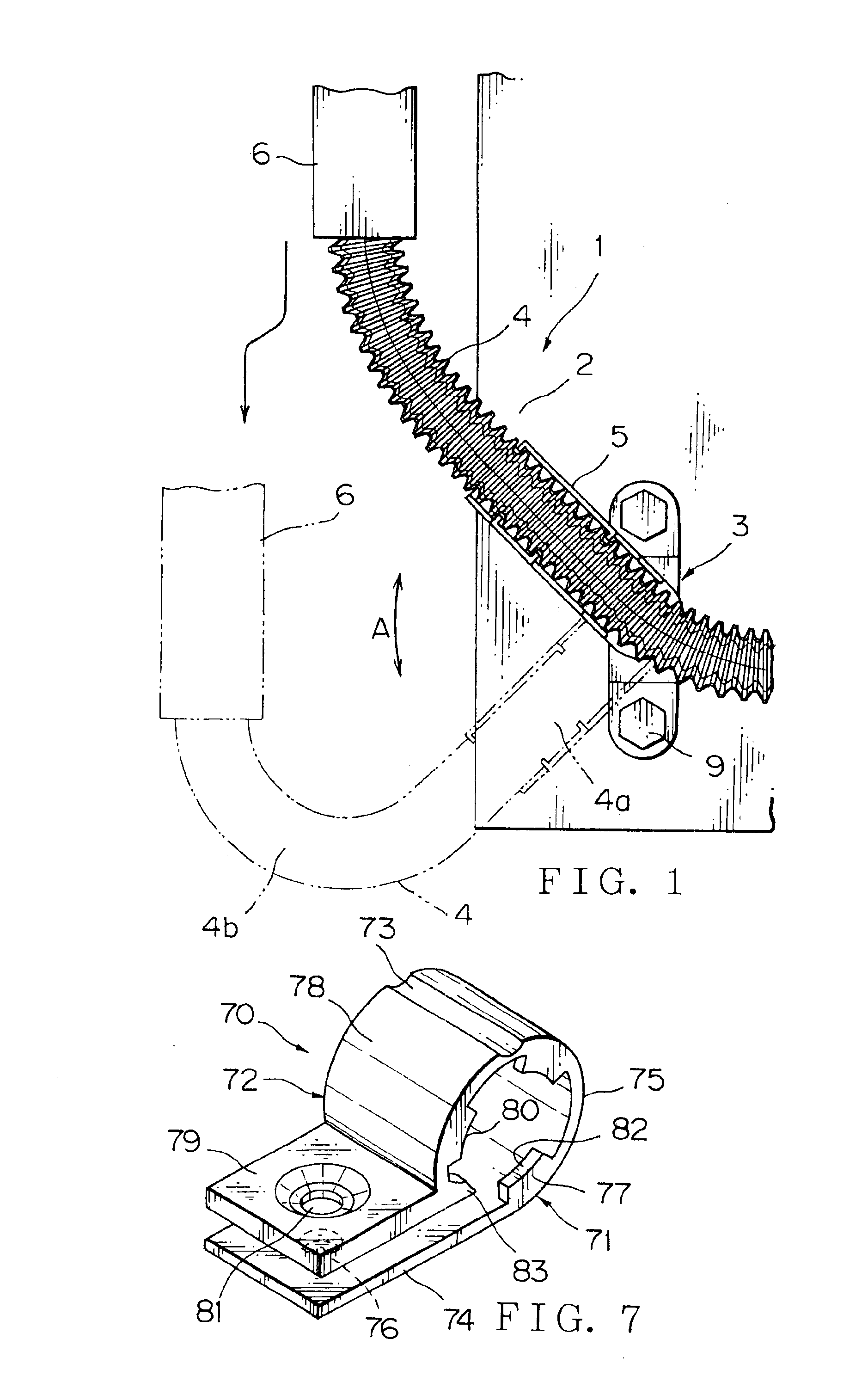
[0120]FIG. 7 shows a harness support 70 turnably supporting a harness guide. When the harness support 70 is directly turnably supported by the car body without the base member 9, the harness support 70 is called as a pivotal harness guide. The harness support 70 may be secured to the car body such that the corrugated tube is turnable in its circumferential direction to prevent an abnormal torsional deformation of the corrugated tube.

[0121]The harness support 70 has a configuration similar to a unitary combination of the cradle 32 and the cap 33 of FIG. 4. The harness support 70 consists of a lower cradle 71 and an upper cap (cover) 72 unitarily formed with the lower cradle 71 via a hinge 73 having a small thickness.

[0122]The cradle 71 has a horizontal plate 74 and a generally semicircle curbed portion 75 contiguous with the plate 74. The plate 74 has a hole 76 for turning and supporting the harness support 70. The curbed portion 75 has an inner surface formed with two arc-shaped loc...


PUM


Abstract

A pivotal harness guide 3 is provided in a side of a car body 1 or a sliding door, and a corrugated tube 4 is secured to the harness guide. The corrugated tube 4 may be held turnably in a circumferential direction of the corrugated tube 4 by the harness guide. The harness guide 3 has a locking projection that engages with a groove formed in the corrugated tube 4. The harness guide 3 has a harness support member 5 for securing the corrugated tube 4 to the harness guide and a base member 9 for turnably connecting the harness support member to the base member by a connecting member, and the base member is secured to the car body or the sliding door. The corrugated tube 4 may be turnable together with harness supporting cradles within a cylindrical wall formed in a panel of the car body.

Description

CROSS REFERENCE TO RELATED APPLICATIONS[0001]This application is a divisional application of U.S. patent application Ser. No. 10 / 097,094 filed Mar. 14, 2002 now U.S. Pat No. 6,700,064.BACKGROUND OF THE INVENTION[0002]1. Field of the Invention[0003]The present invention relates to a wiring harness arrangement assembly for transmission of a power and signals between a car body side and electrical equipment including auxiliary instruments disposed in a sliding door side. Particularly, the wiring harness is covered by a corrugated tube, and the wiring harness arrangement assembly has a pivotal harness guide to allow a sufficient flexibility and an appropriate torsional performance of the wiring harness received in the corrugated tube.[0004]2. Related Art[0005]A one-box car or a wagon has a sliding door for which various types of electric supply units have been proposed to supply a power from a power source disposed in a car body side to the sliding door and to transmit electrical signal...

Claims


Application Information

Patent Timeline
IPC IPC(8): B60R16/02
CPCB60R16/0215
Inventor AOKI, TOHRUDOSHITA, KENICHITSUNODA, MITSUNORIFUKUMOTO, RYOICHI
Owner YAZAKI CORP
Why Eureka
Try Eureka