Earth Leakage Breaker

a leakage breaker and earth technology, applied in the field of earth leakage breaker, can solve the problems of leakage breaking operation, leakage breaking erroneously, trouble and bother on the part of electricity users

Inactive Publication Date: 2005-04-19
MITSUBISHI ELECTRIC CORP +1
View PDF18 Cites 9 Cited by
  • Summary
  • Abstract
  • Description
  • Claims
  • Application Information

AI Technical Summary

Problems solved by technology

However, in such an earth leakage breaker, even in case of a lightning surge not so large as to short-circuit and break the lightning arrester 3, an electric current flows to an earth through the lightning arrester 3 and is detected by the leakage trip circuit 45, thereby erroneously occurring an earth leakage breaking operation.
In some cases, however, during the propagation of waveform through a distribution line, a waveform change may take place from the waveform peculiar to the lightning surge due to line constant of the distribution line and others, whereby an earth leakage breaking occurs erroneously.
Such a malfunction of the earth leakage breaker 4 causes a power failure of the load 2, which results in trouble and bothers on the part of electricity users.
On the other hand, if the invading lightning surge is of a large energy, a power supply short circuit accident may occur due to damage of the lightning arrester 3, and therefore the connection arrangement in FIG. 16 is not recommendable.
As described above, in the conventional connection of the lightning arrester to the earth leakage breaker, a problem exists in that it is impossible to prevent both malfunction caused by a lightning surge and occurrence of a power supply short circuit accident.

Method used


Image

  • Earth Leakage Breaker
  • Earth Leakage Breaker
  • Earth Leakage Breaker

Examples


embodiment 1

[0033]The invention is hereinafter described in more detail with reference to the accompanying drawings.

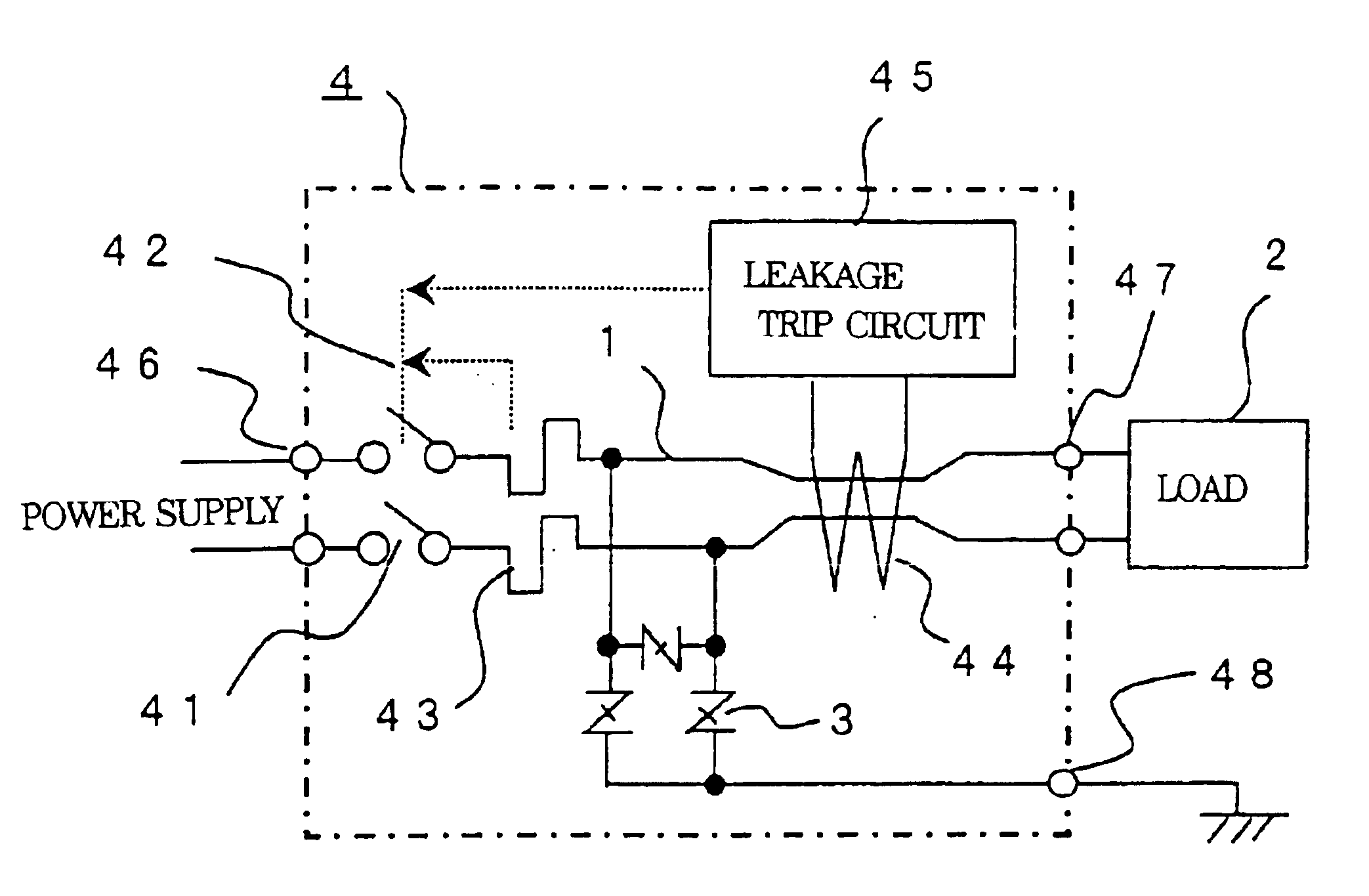
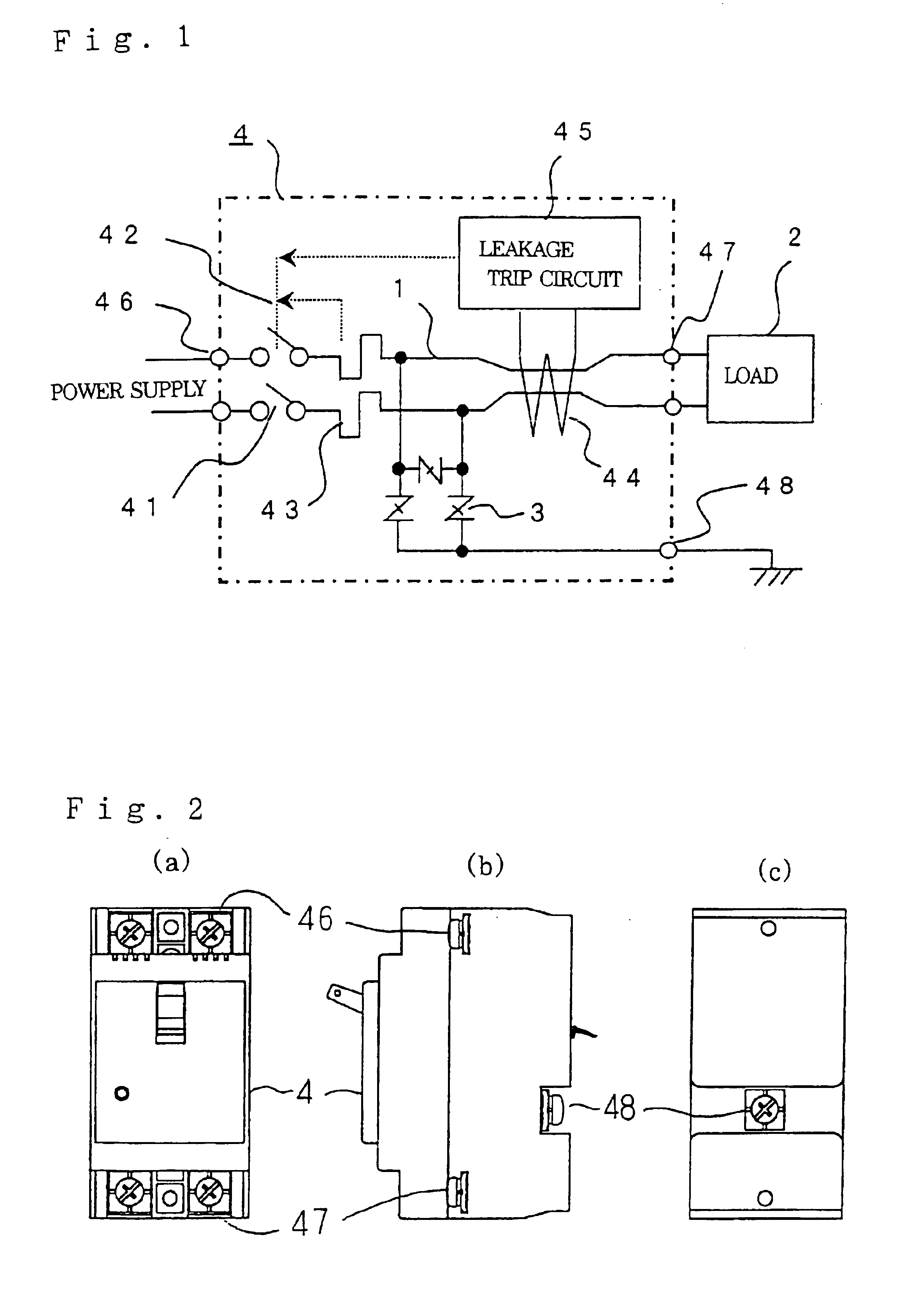
[0034]FIG. 1 is a diagram showing a connection arrangement between an earth leakage breaker and a lightning arrester according to Embodiment 1 of the invention, and FIGS. 2(a), (b) and (c) are exterior views each showing the earth leakage breaker of Embodiment 1. In the drawings, reference numerals 1 to 4 and 41 to 45 are the same as those in the description of the above-mentioned conventional devices. Numeral 46 is a power supply side terminal of the earth leakage breaker 4, numeral 47 is a load side terminal, and numeral 48 is an earth terminal disposed in an outer shell casing of a housing of the earth leakage breaker 4. In the earth leakage breaker of this Embodiment 1, the lightning arrester 3 is disposed in the housing of the earth leakage breaker 4. The electric path 1 is formed so that the contact 41, the overcurrent detector section 43, and the zero phase current transfor...

embodiment 2

[0036]In the foregoing Embodiment 1, the lightning arrester 3 is disposed in the casing of the earth leakage breaker 4. However, in practical use, the lightning arrester 3 of different performance and different type is required depending upon the place where the earth leakage breaker 4 is installed and the kind of the electrical machinery to be protected. This Embodiment 2 is aimed to improve this point.

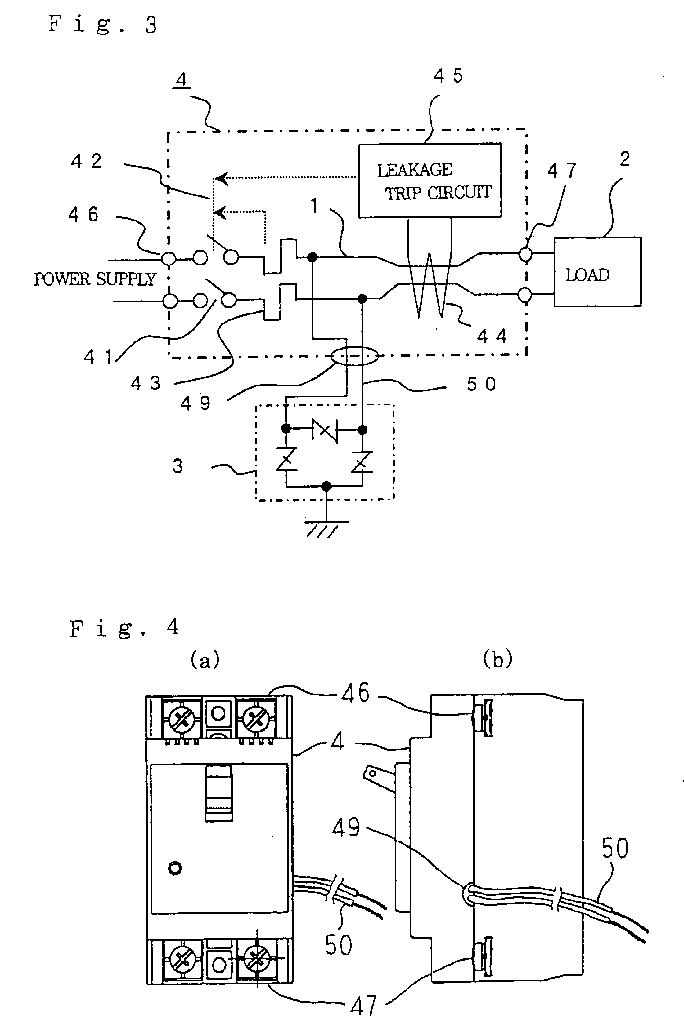
[0037]FIG. 3 is a diagram showing a connection arrangement between an earth leakage breaker and a lightning arrester according to Embodiment 2 of the invention and FIGS. 4(a) and (b) are exterior views each showing the earth leakage breaker according to Embodiment 2.

[0038]In the drawings, numerals 1 to 4 and 41 to 47 are the same as those described in the foregoing Embodiment 1.

[0039]Numeral 49 is an opening provided on the housing outer shell casing of the earth leakage breaker 4, numeral 50 is a lead wire for connection to the lightning arrester 3, and in which one end is connected...

embodiment 3

[0040]FIG. 5 is a diagram showing a connection arrangement between an earth leakage breaker and a lightning arrester according to Embodiment 3 of the invention, FIGS. 6(a) and (b) are exterior views each showing the earth leakage breaker of Example 1 according to Embodiment 3, and FIGS. 7(a), (b) and (c) are exterior views each showing the earth leakage breaker of Example 2 according to Embodiment 3.

[0041]In the drawings, numerals 1 to 4 and 41 to 47 are the same as those described in the foregoing Embodiment 1. Numeral 5 is a lightning arrester box in the form of a housing different from the earth leakage breaker 4, and the lightning arrester 3 is accommodated in the lightning arrester box 5. Numeral 51 is an earth terminal, and numeral 52 is a connector. The connector 52 is composed of a portion connected between the overcurrent detector section 43 and the zero phase current transformer 44 in the earth leakage breaker 4 and a portion connected to the lightning arrester 3 in the li...


PUM


Abstract

Malfunction of an earth leakage breaker due to a lightning surge is prevented, and when a lightning arrester is short-circuited and damaged by a high-level lightning surge, a power supply short circuit is prevented.
A contact 41, an overcurrent detector section 43, and a zero phase current transformer 44 are disposed in order from a power supply side to a load side, and a lightning arrester 3 is connected between the overcurrent detector section 43 and the zero phase current transformer 44.

Description

TECHNICAL FIELD[0001]The present invention relates to an earth leakage breaker capable of preventing a malfunction caused by a lightning surge and protecting from a short circuit when a lightning arrester is damaged by a lightning surge.BACKGROUND ART[0002]Hitherto, circuits shown in FIG. 15 and FIG. 16 are known as examples of a circuit in which an earth leakage breaker and a lightning arrester are connected to each other in order to protect electrical machinery and apparatus from a lightning surge.[0003]In the drawings, reference numeral 1 is an electric path, numeral 2 is an electrical machinery acting as a load, numeral 3 is a lightning arrester, and numeral 4 is an earth leakage breaker. The earth leakage breaker 4 is comprised of a contact 41 for switching on / off the electric path 1, a switch mechanism 42 composed of a toggle link mechanism for opening and closing the foregoing contact 41, an overcurrent detector section 43 composed of an electromagnetic device including a bim...

Claims


Application Information

Patent Timeline
Patent Type & Authority Patents(United States)
IPC IPC(8): H02H1/00H02H3/33H02H3/32H01H83/00H01H83/22H02H9/04H02H3/08H02H3/10
CPCH02H1/0038H02H3/334H01H83/226H02H9/041H02H3/105H01H69/01
Inventor ANAMURA, TAKASHIHOSOGAI, SETSUOTAKAHATA, KUNIHIKO
Owner MITSUBISHI ELECTRIC CORP
Why Eureka
Try Eureka