

Boring, milling machine primed by straight-line driven portal shaped in zero phase on beam of magnetic suspension
A technology of linear drive and control method, applied in the field of numerical control, can solve problems such as inability to guarantee synchronization performance, equipment damage, etc.
- Summary
- Abstract
- Description
- Claims
- Application Information
AI Technical Summary
Problems solved by technology
Method used
Image

Examples
Embodiment Construction
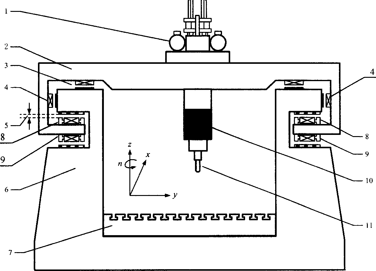
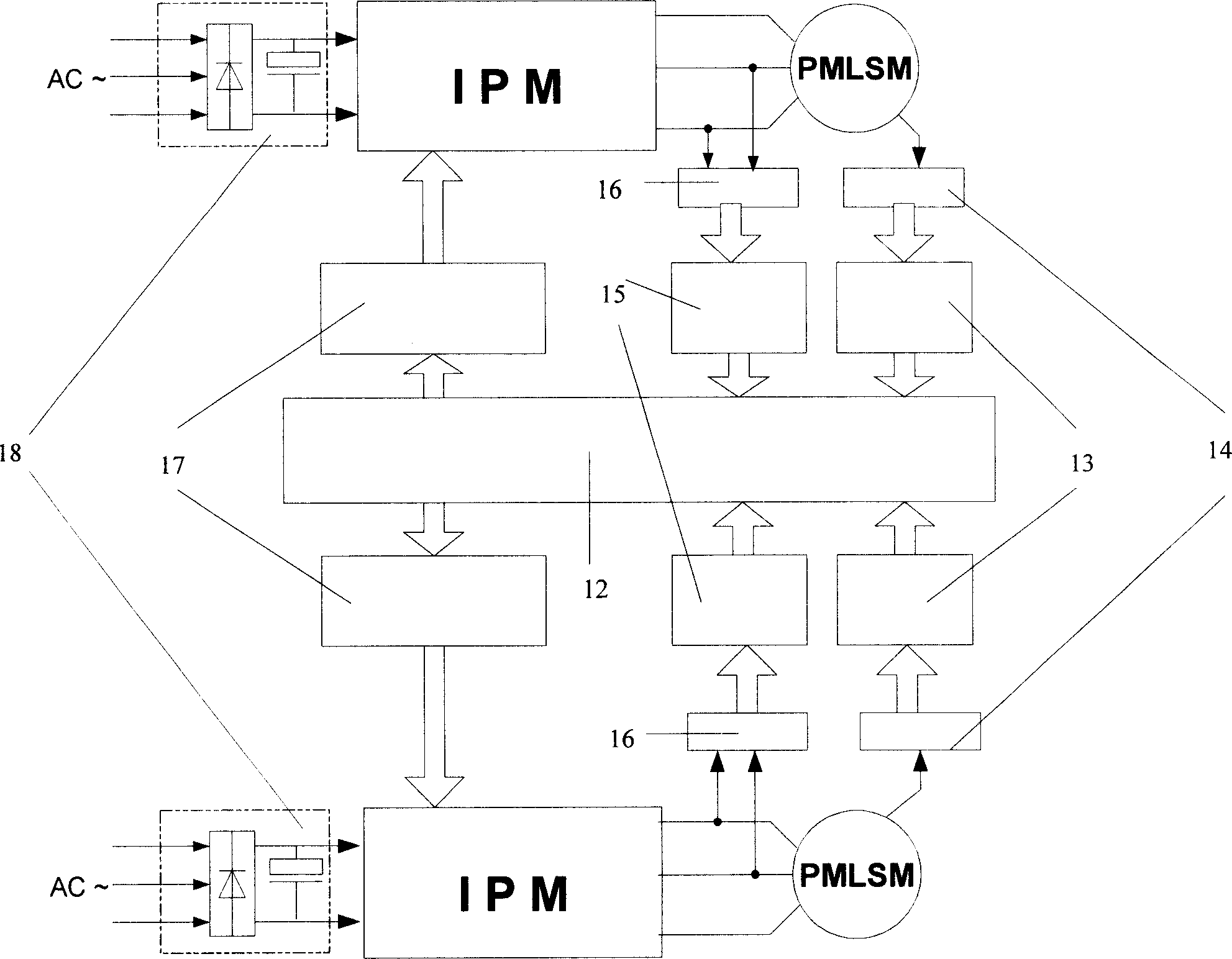
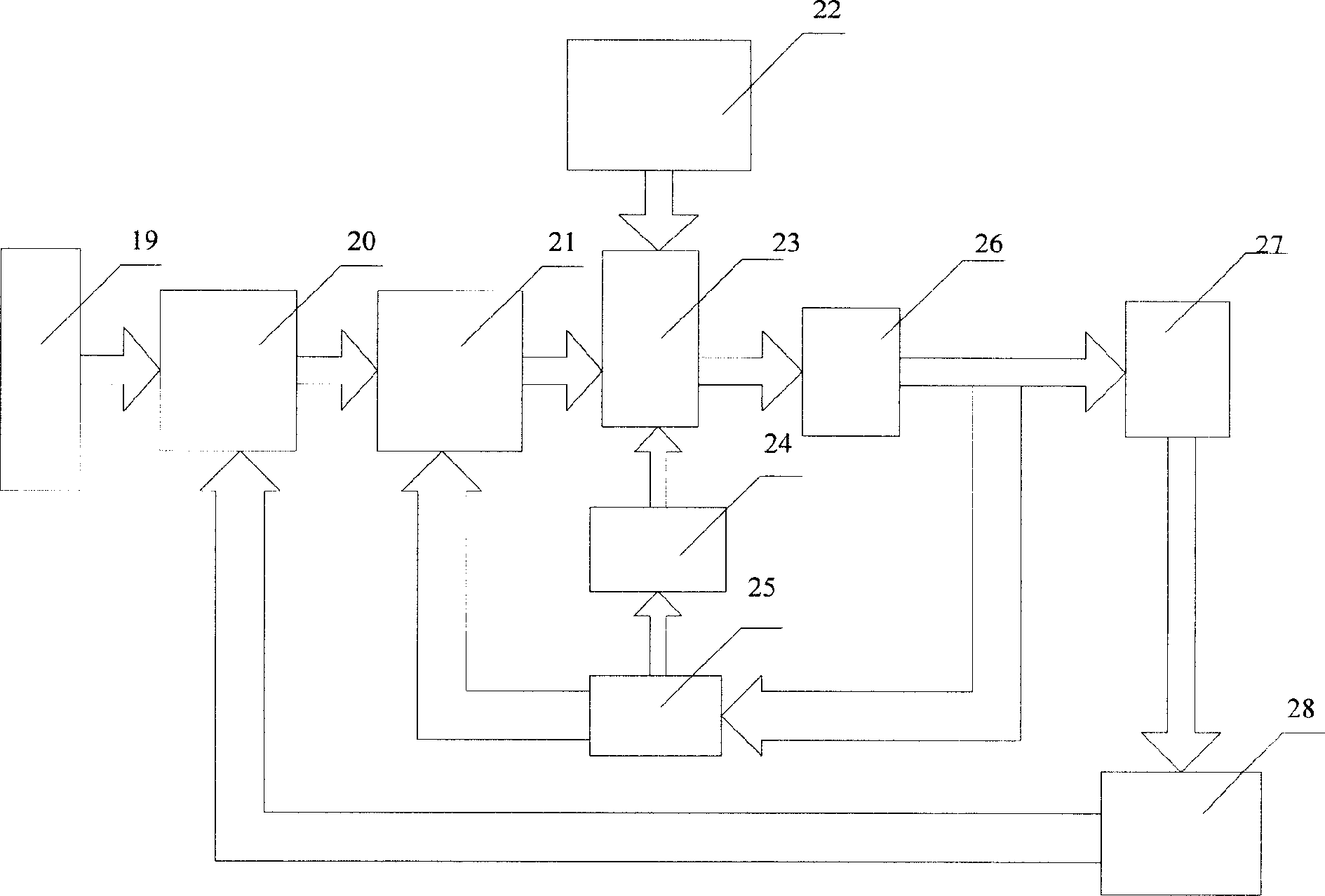
[0112] A preferred embodiment of the present invention see figure 1 , Figure 11 and Figure 12.
[0113] Such as figure 1 As shown, the gantry mobile processing machine driven by the magnetic levitation beam linear motor part includes a servo unit (including servo motor and sensor, servo driver), box-type beam, X-direction linear motor, guide unit (including motor, sensor and driver), beam suspension Air gap, integrated bed, worktable, main suspension electromagnet, compensation electromagnet, spindle unit (spindle drive motor and sensor, spindle driver) and tool, the main suspension electromagnet coil is connected with the inner extension of the end of the beam, and the armature On the bed, there are two rows on the left and right, which act as a suspension beam. The connection between the compensation electromagnet and the main suspension electromagnet is similar, that is, the main suspension electromagnet is connected to the top of the inner extension of the beam end, and...
PUM
 Abstract
Description
Claims
Application Information