Electric leak breaker for self-test

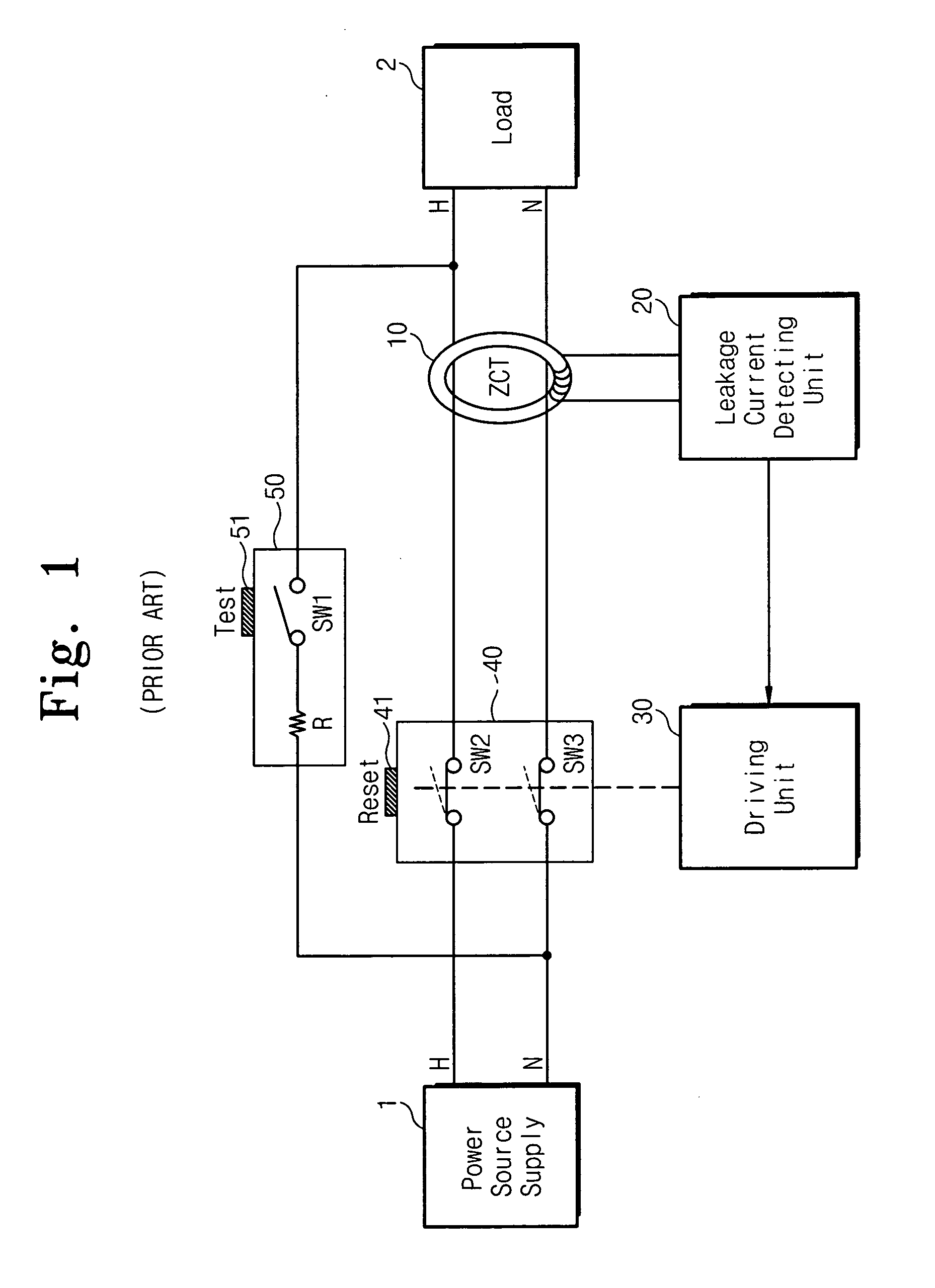
a self-testing, electric leak technology, applied in the direction of emergency protective circuit arrangement, emergency protective arrangement for limiting excess voltage/current, electric apparatus, etc., can solve the problem of inconvenient pressing the reset button b>41/b>

Inactive Publication Date: 2005-11-03
CHE IL ELECTRIC WIREING DEVICES
View PDF1 Cites 26 Cited by
  • Summary
  • Abstract
  • Description
  • Claims
  • Application Information

AI Technical Summary

Benefits of technology

[0010] Accordingly, the present invention is directed to an electric leak breaker capable of periodically performin...

Problems solved by technology

Furthermore, there is an inconvenience to push th...

Method used


Image

  • Electric leak breaker for self-test
  • Electric leak breaker for self-test
  • Electric leak breaker for self-test

Examples


Embodiment Construction

[0019] The present invention will be described more fully hereinafter with reference to the accompanying drawings, in which exemplary embodiments of the invention are shown.

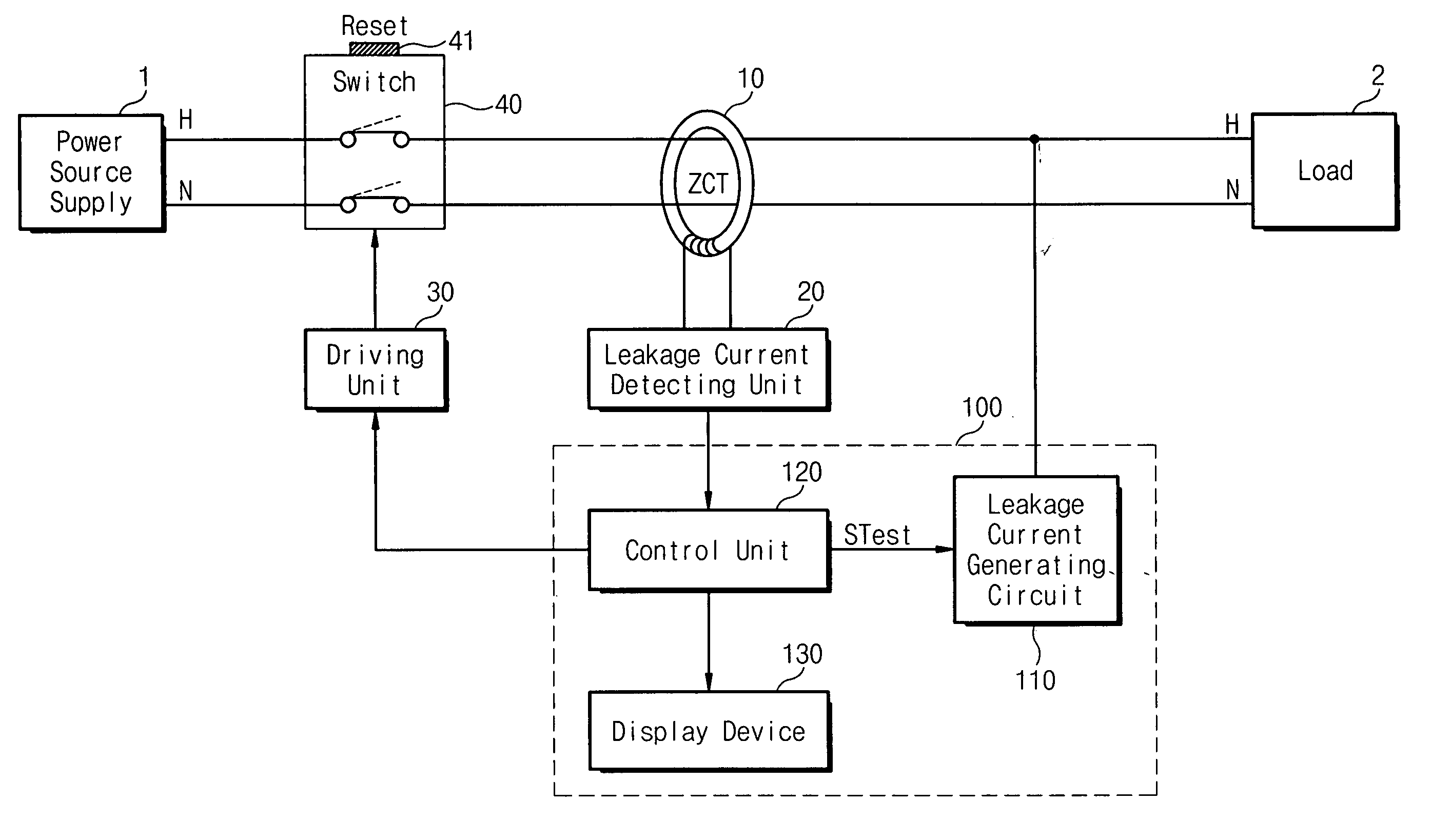
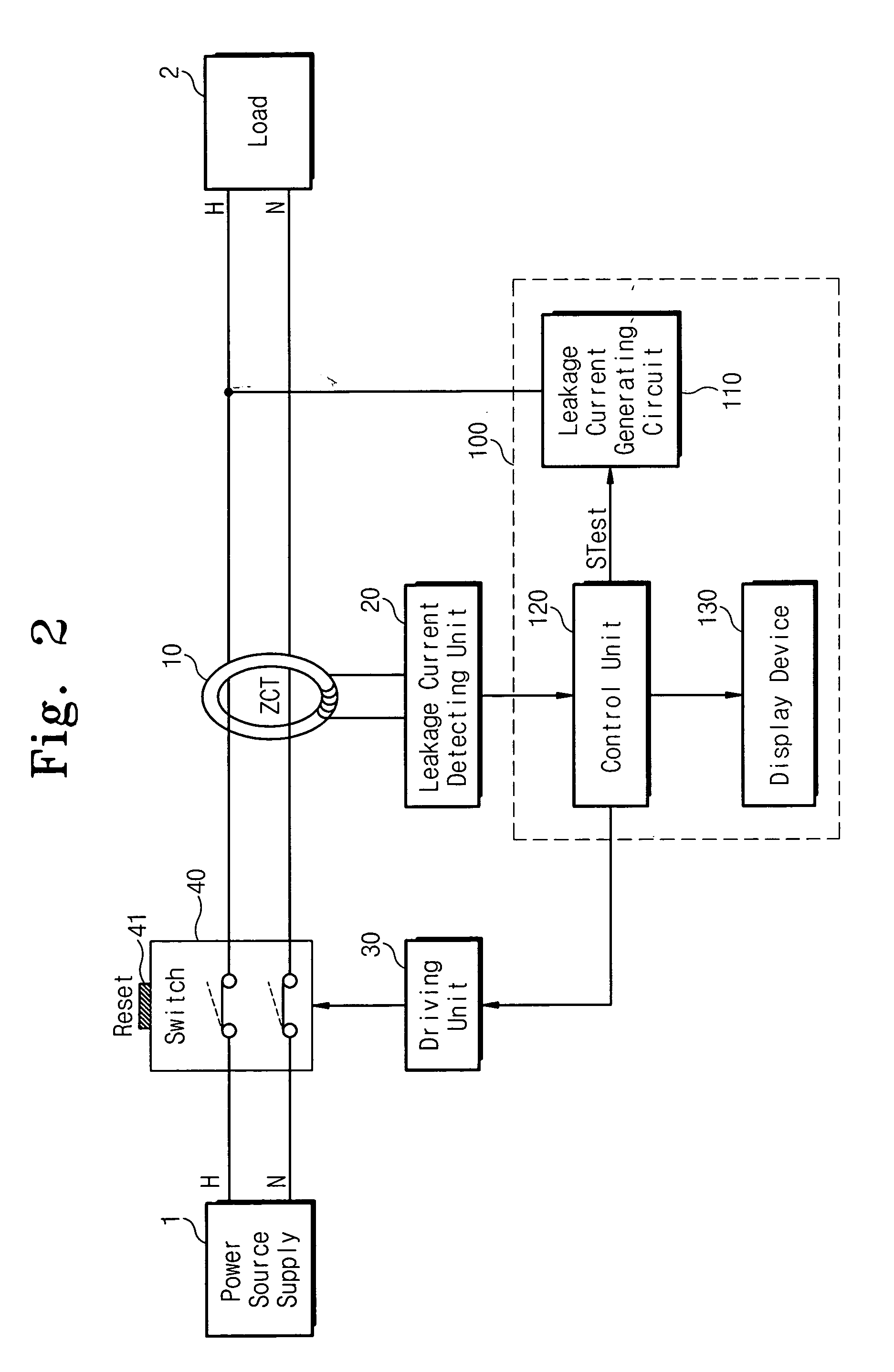
[0020]FIG. 2 is a schematic block diagram showing an electric leak breaker according to the present invention. In this case, the same references shown in FIG. 1 indicate the same members performing the same functions. An electric leak breaker for self-test according to the present invention is automatically capable of testing whether the electric leak breaker is normally operated by periodically generating leakage current to a power supply line. In addition, since the electric leak breaker may be tested without breaking the power supply line, it is possible to overcome an inconvenience of pushing a reset button.

[0021] Referring to FIG. 2, the electric leak breaker for self-test comprises power supply lines H and N for connecting a power source supply 1 with a load 2, a zero-phase current transformer (ZCT) 10 fo...


PUM


Abstract

The present invention disclosed herein is an electric leak breaker for self-test. The electric leak breaker for self-test comprises power supply lines for connecting a power source supply with a load; a zero-phase current transformer installed on the power supply lines and for sensing a current difference between the power supply lines; a leakage current detecting unit connected to the zero-phase current transformer for detecting whether a leakage current occurs to generate a detection signal; a driving unit for making the power supply lines broken when a critical voltage or a voltage higher than the critical voltage is provided; and a self-test unit for periodically inducing the leakage current at the power supply lines to test whether the leakage detecting unit is normally operating, and for providing a lower voltage than the critical voltage to the driving unit to test whether the driving unit is normally operating in a self-test operation. According to the present invention, it is possible to periodically test the electric leak breaker as well as to overcome an inconvenience to push a reset button.

Description

[0001] This application claims priority from Korean Patent Application No. 2004-30319, filed on Apr. 30, 2003, the contents of which is herein incorporated by reference in its entirety. FIELD OF THE INVENTION [0002] This disclosure generally relates to electric leak breakers and, more specifically, to an electric leak breaker capable of self-testing periodically. BACKGROUND OF THE INVENTION [0003] In general, electric leak breakers perform functions to sense a leakage current and breaks electric current from loads when leakage current is generated at loads. There is an advantage to prevent the fire as well as shock caused by a leakage of electricity. [0004]FIG. 1 is a schematic diagram showing an electric leak breaker according to a conventional art. The electric leak breaker shown in FIG. 1 is disclosed in Korean Utility Model Patent Publication (Application No. 20-2003-30832). Referring to FIG. 1, the electric leak breaker according to the conventional art comprises power supply l...

Claims


Application Information

Patent Timeline
IPC IPC(8): H02H1/06H02H3/26H02H3/00H02H3/33
CPCH02H3/335H02H1/06H02H3/26
Inventor KIM, BYUNG-KOOK
Owner CHE IL ELECTRIC WIREING DEVICES
Why Eureka
Try Eureka