Power feed control device

a control device and feed technology, applied in the direction of electric devices, emergency protective arrangements for limiting excess voltage/current, transportation and packaging, etc., can solve the problem of inability to accurately detect small unbalanced current always flowing through, and inability to detect such an electrical leakage whose magnitude cannot be detected, etc. problem, to achieve the effect of accurately detecting the occurrence of electrical leakag

Active Publication Date: 2011-05-26
PANASONIC CORP
View PDF2 Cites 31 Cited by
  • Summary
  • Abstract
  • Description
  • Claims
  • Application Information

AI Technical Summary

Benefits of technology

[0019]The present invention can provide a power feed control device which includes a voltage detection circuit and is configured to be able to accurately detect occurrence of electrical leakage.

Problems solved by technology

Therefore, a small unbalanced current always flows through the zero-phase-sequence current transformer ZCT.
Therefore, this conventional example cannot detect such an electrical leakage whose magnitude is less or comparable with the magnitude of the current I3.
That is, this conventional example cannot accurately detect occurrence of electrical leakage.

Method used


Image

  • Power feed control device
  • Power feed control device
  • Power feed control device

Examples


Embodiment Construction

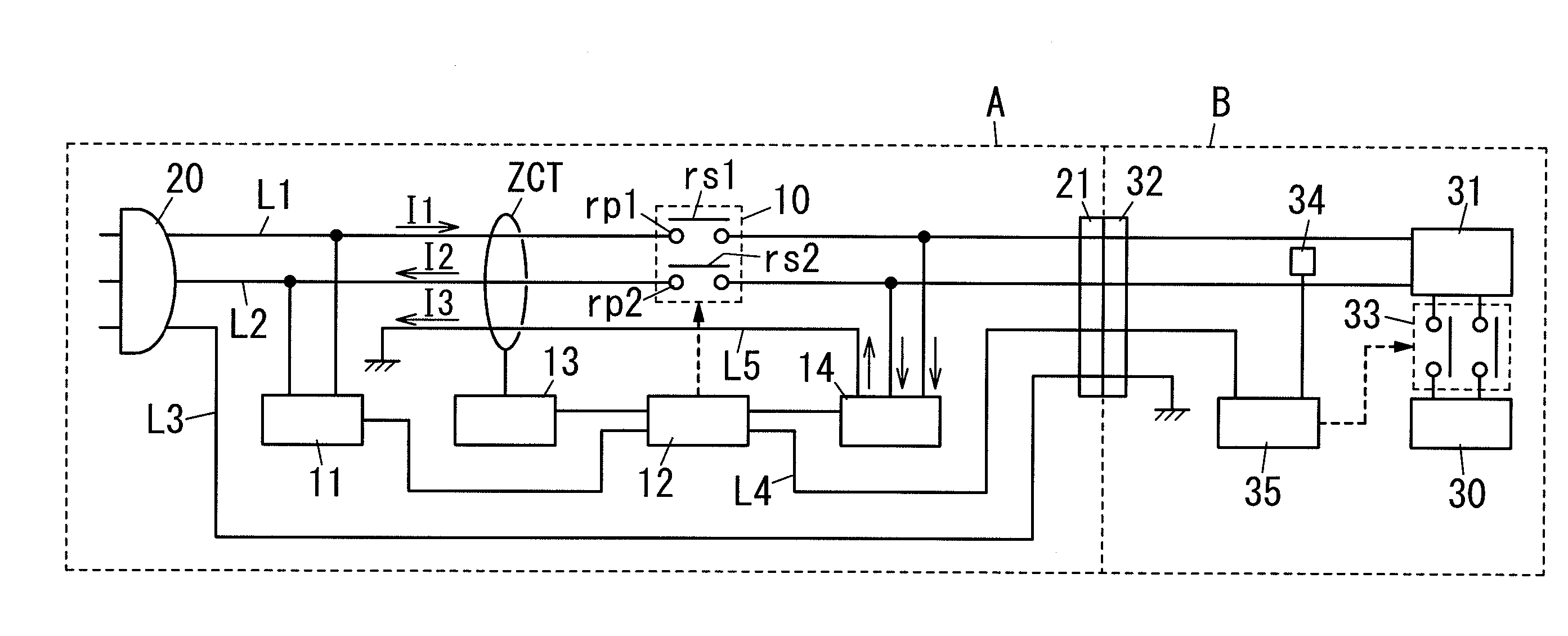
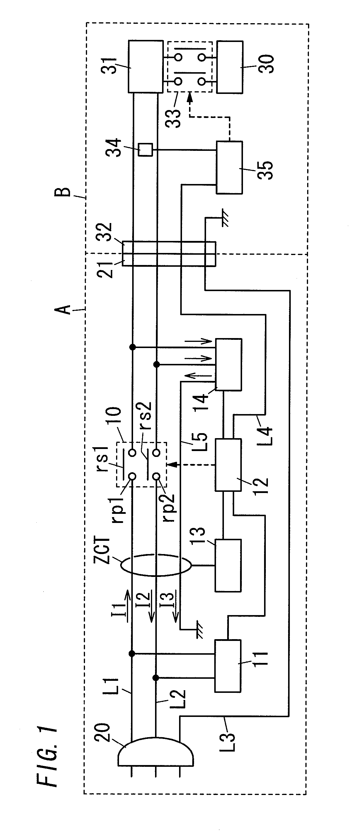
[0024]An embodiment of the present invention is explained with reference to attached drawings. In FIG. 1, each solid arrows shows the flowing direction of current. It should be noted that each of the current flowing in the first conductive wire L1 and the second conductive wire L2 is alternating current. Therefore, the flowing directions of the currents alternately vary with time.

[0025]A power feed control device like the present embodiment can be used for such as a plug-in hybrid vehicle or an electric vehicle. An electric vehicle is used for explaining the operation of the present embodiment.

[0026]An electric vehicle B includes a battery 30, an on-vehicle charger 31, a connector 32, a relay 33, a detection part 34 and a charge control device 35. The battery 30 is configured to supply a motor (not shown in figure), which is a drive source of the electric vehicle B, with electric power. The on-vehicle charger 31 is configured to convert AC power supplied from a commercial power supp...


PUM


Abstract

A branch wire L5 from the voltage detection circuit 14 is inserted in the zero-phase-sequence current transformer ZCT in the direction from the load side to the external power supply side. For this configuration, the zero-phase-sequence current transformer ZCT is to detect unbalance of the sum of current flowing in the first and second conductive wires L1, L2 and the current flowing in the branch wire L5. Therefore, the present invention can accurately detect occurrence of electrical leakage.

Description

TECHNICAL FIELD[0001]The invention relates to a power feed control device.BACKGROUND ART[0002]In the past, there has been provided a power feed control device A as shown in FIG. 3A. For example, the power feed control device A (for example, refer to Japanese Patent Application Laid-Open No. 2009-234392) includes a plug 20 being configured to be attached to an external power supply such as a commercial AC power supply of 100V, a load connector 21 being configured to be attached to a load such as a vehicle, and a feed line. The feed line includes a first conductive wire L1 corresponding to a live wire and a second conductive wire L2 corresponding to a neutral wire. The power feed control device A is used, for example, for supplying an on-vehicle charger with electric power. The on-vehicle charger is configured, for example, to charge up a battery which a plug-in hybrid vehicle or an electric vehicle is equipped with.[0003]For details, the power feed control device A includes the first...

Claims


Application Information

Patent Timeline
Patent Type & Authority Applications(United States)
IPC IPC(8): H02H3/16
CPCB60L3/0069B60L11/1814B60L11/1824H02H3/334Y02T90/121Y02T90/12Y02T90/127Y02T90/14Y02T10/7005Y02T10/7072B60L53/24Y02T10/70
Inventor WATANABE, HIROTOSHIMUKAI, TATSUYAMORI, SHIROFUKUO, NAOKIGOTOU, KIYOSIKAKIUCHI, KOUJINAKAMURA, SHINICHI
Owner PANASONIC CORP
Why Eureka
Try Eureka