
Scroll bars with user feedback

a scroll bar and user feedback technology, applied in the field of computer systems and software, can solve the problems of limiting the narrowness of the scroll bar, the general reasonableness of the user interface, and the complexity of the user interfa

Inactive Publication Date: 2005-04-19
ORACLE INT CORP
View PDF20 Cites 102 Cited by
  • Summary
  • Abstract
  • Description
  • Claims
  • Application Information

AI Technical Summary

Benefits of technology

[0009]The scroll button is drawn using a transparency effect, making it possible for the user to see any data that may be in the part of the screen that is overlaid by the scroll button. In fact, in some embodiments, the transparency with which the scroll button is displayed is a function of how close the cursor is to the scroll button.
[0010]The same type of transparency effect can be applied to the scroll bar itself. That is, when the cursor is relatively far from the scroll bar, the scroll bar may be completely invisible. However, as the cursor approaches the scroll bar, the scroll bar and / or the scroll button become progressively more visible, that is, they become more nearly opaque.
[0012]The scroll bar techniques disclosed herein are utilizable for controlling functions or objects in a three-dimensional virtual world and can be extended to controlling functions in an N-dimensional space. In an N-dimensional space, where N is greater than 2, the path followed by the scroll bar can be arbitrary, that is, the scroll bar is not constrained to follow a linear path. This provides great utility when moving objects or adjusting controls in a three-dimensional space.

Problems solved by technology

These are generally reasonably unobstrusive when there is no more than a single scroll bar for each direction on a display page.
Using traditional approaches, there is a limit as to how narrow a scroll bar can be since the user needs to be able to position the cursor over the scroll button in order to move it.
As graphical user interfaces become more complex, traditional scroll bars tend to dominate too much of the visual content of the screen.

Method used


Image

  • Scroll bars with user feedback
  • Scroll bars with user feedback
  • Scroll bars with user feedback

Examples


Embodiment Construction

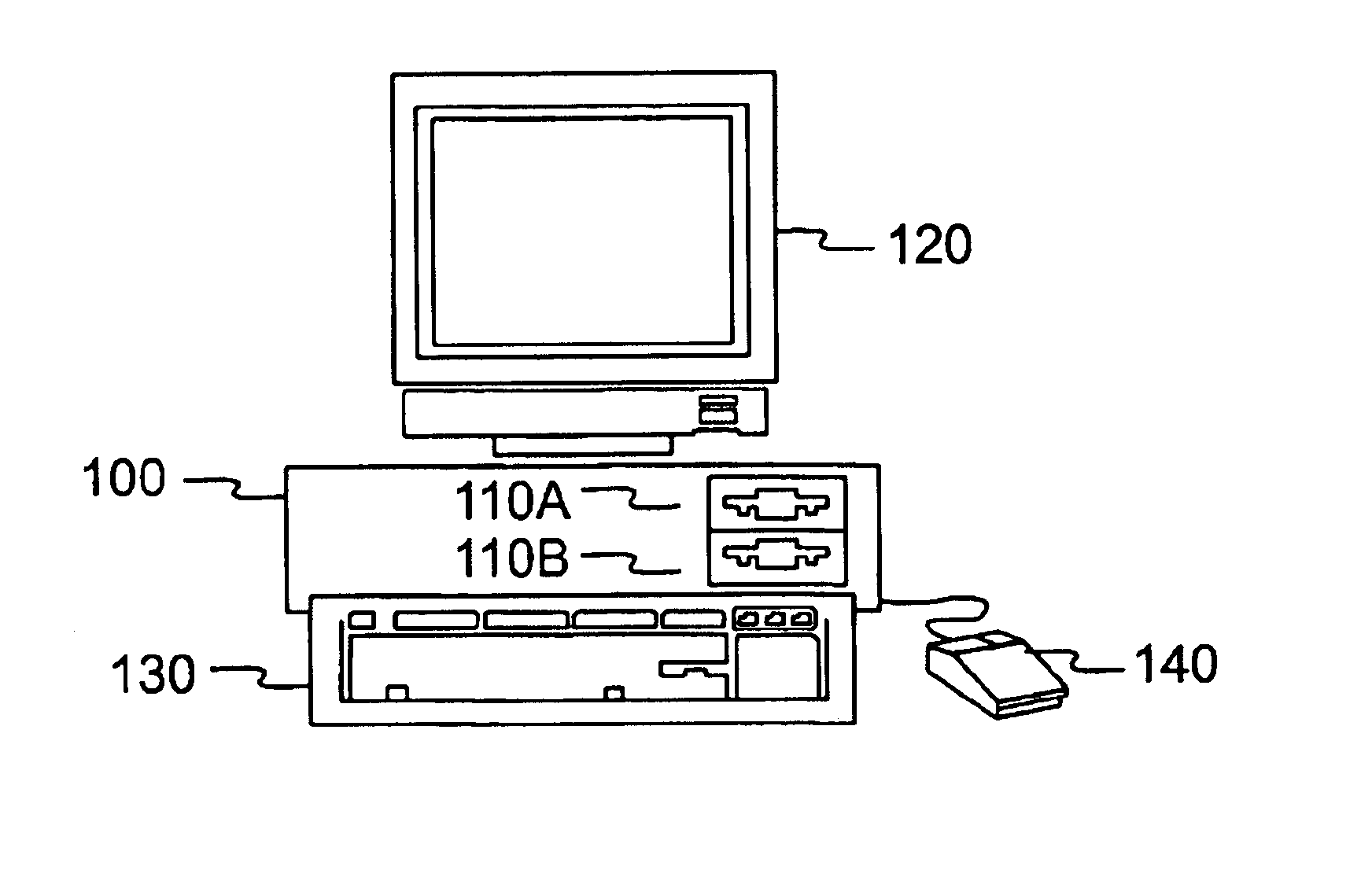
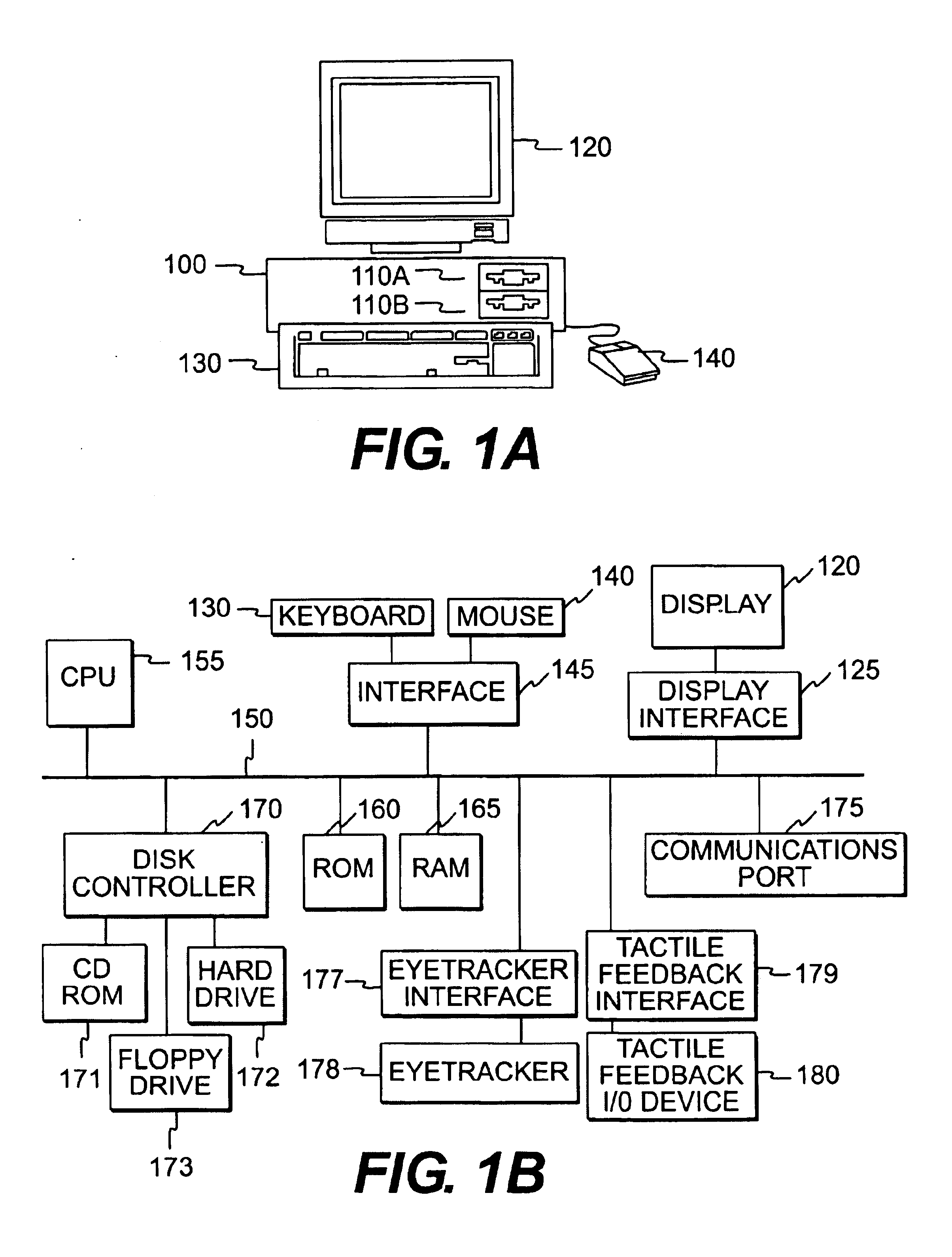
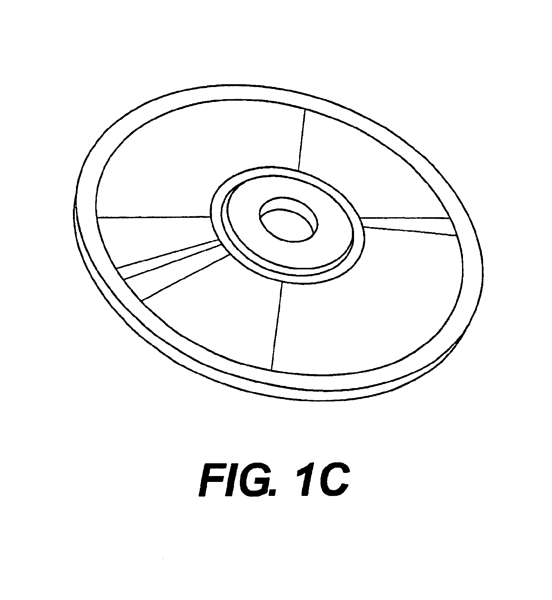
[0039]FIG. 1A illustrates a computer of a type suitable for carrying out the invention. Viewed externally in FIG. 1A, a computer system has a central processing unit 100 having disk drives 110A and 110B. Disk drive indications 110A and 110B are merely symbolic of a number of disk drives which might be accommodated by the computer system. Typically, these would include a floppy disk drive such as 110A, a hard disk drive (not shown externally) and a CD ROM drive indicated by slot 110B. The number and type of drives varies, typically, with different computer configurations. The computer has the display 120 upon which information is displayed. A keyboard 130 and a mouse 140 are typically also available as input devices. Preferably, the computer illustrated in FIG. 1A is a SPARC workstation from Sun Microsystems, Inc.

[0040]FIG. 1B illustrates a block diagram of the internal hardware of the computer of FIG. 1A. A bus 150 serves as the main information highway interconnecting the other com...


PUM


Abstract

A graphical user interface uses scroll bars having a single pixel width and a much larger scroll button or thumb. Both the scroll bar and the scroll button may be controlled to have selective degrees of transparency so that they underlying image information may be seen under certain conditions. In one application, the scroll bar itself is invisible until a cursor approaches to within a specified proximity. The graphical user interface permit scroll bars to be displayed which follow an arbitrary path in either two or three dimensions.

Description

BACKGROUND OF THE INVENTION[0001]1. Field of the Invention[0002]The invention relates to computer systems and software and, more particularly, to a graphical user interface having scroll bars which are a single pixel wide and which, under certain conditions, may be invisible.[0003]2. Description of Related Art[0004]Scroll bars are known in the art which are rendered as a rather wide stripe running along the border of the scrollable area. More specifically, scroll bars are typically rendered as a vertical stripe when controlling scrolling in a vertical direction and are rendered as a horizontal stripe when controlling scrolling in a horizontal direction. These are generally reasonably unobstrusive when there is no more than a single scroll bar for each direction on a display page.[0005]Scroll bars have a scroll button (sometimes called a scroll “thumb” or “elevator”) which the user grabs in order to move the view of the display controlled by the scroll bar. When the user selects a sc...

Claims


Application Information

Patent Timeline
IPC IPC(8): G06F3/00G06F3/033G09G5/34G06F3/01G06F3/0485
CPCG06F3/013G06F3/016G06F3/04855G06F3/04815G09G2340/10G06F2203/014G06F2203/04804
Inventor NIELSEN, JAKOB
Owner ORACLE INT CORP
Learn More