
Universal receptacles for interchangeably receiving different removable computer drive carriers

a technology for computer drives and chassis, applied in the field of receptacles, can solve the problems of increasing the cost and complexity of the computer system, and the inability of different removable carriers in which serial and parallel connected computer drives are enclosed to be inserted into the same drive bay of the chassis, so as to maximize the flexibility of the computer system

Inactive Publication Date: 2005-04-19
CRU ACQUISITION GROUP
View PDF3 Cites 17 Cited by
  • Summary
  • Abstract
  • Description
  • Claims
  • Application Information

AI Technical Summary

Benefits of technology

[0007]A universal receiving frame according to a first embodiment of this invention is disclosed to be mounted in a drive bay of a chassis or storage enclosure that is interfaced with a host computer. The universal receiving frame is configured so as to be automatically adapted to interchangeably receive different removable computer drive carriers regardless of whether the portable computer (e.g. disc) drive thereof is connected for serial or parallel operation. The ability of a single receiving frame to automatically accommodate different removable carriers and both serially and parallel connected computer drives maximizes the flexibility of the computer system and avoids the necessity of having to make alterations to the chassis and / or the portable computer drives.
[0008]The universal receiving frame of this embodiment includes a U-shaped body having a back wall, a pair of side walls and an open front to slidably receive a removable carrier in which either a serial or parallel connected computer drive is housed. A multi-pin backplane connector is mounted on and faces inwardly from the back wall of the U-shaped body so as to be mated to the backplane interface connector of an incoming removable carrier. A printed circuit board that is electrically connected to the multi-pin connector is mounted on and faces outwardly from the back wall of the U-shaped body. A DC power connector and a suitable (e.g. a Serial ATA, parallel ATA, SCSI, Serial Attached SCSI (SAS), or the like) interface are carried on the outwardly facing printed circuit board. In accordance with the present improvement, and to provide the universal receiving frame with the capability of interchangeably receiving different removable carriers having either a serial or parallel connected computer drive, a serial-to-parallel bridge is provided. The serial-to-parallel bridge is implemented as an integrated circuit chip that is connected to the circuit board at the back wall of the universal receiving frame without requiring space consuming wires or cables to be interfaced with the chassis in which the frame is located. In an alternate embodiment, the serial-to-parallel bridge is connected to a circuit board that is mounted on the back wall of the removable carrier.

Problems solved by technology

Consequently, different removable carriers in which serially and parallel connected computer drives are enclosed cannot be inserted in the same drive bay of the chassis unless alterations are first made to the chassis or to the portable computer drives.
Such alterations would typically increase the cost and complexity of the computer system and the remote storage means associated therewith.

Method used


Image

  • Universal receptacles for interchangeably receiving different removable computer drive carriers
  • Universal receptacles for interchangeably receiving different removable computer drive carriers
  • Universal receptacles for interchangeably receiving different removable computer drive carriers

Examples


Embodiment Construction

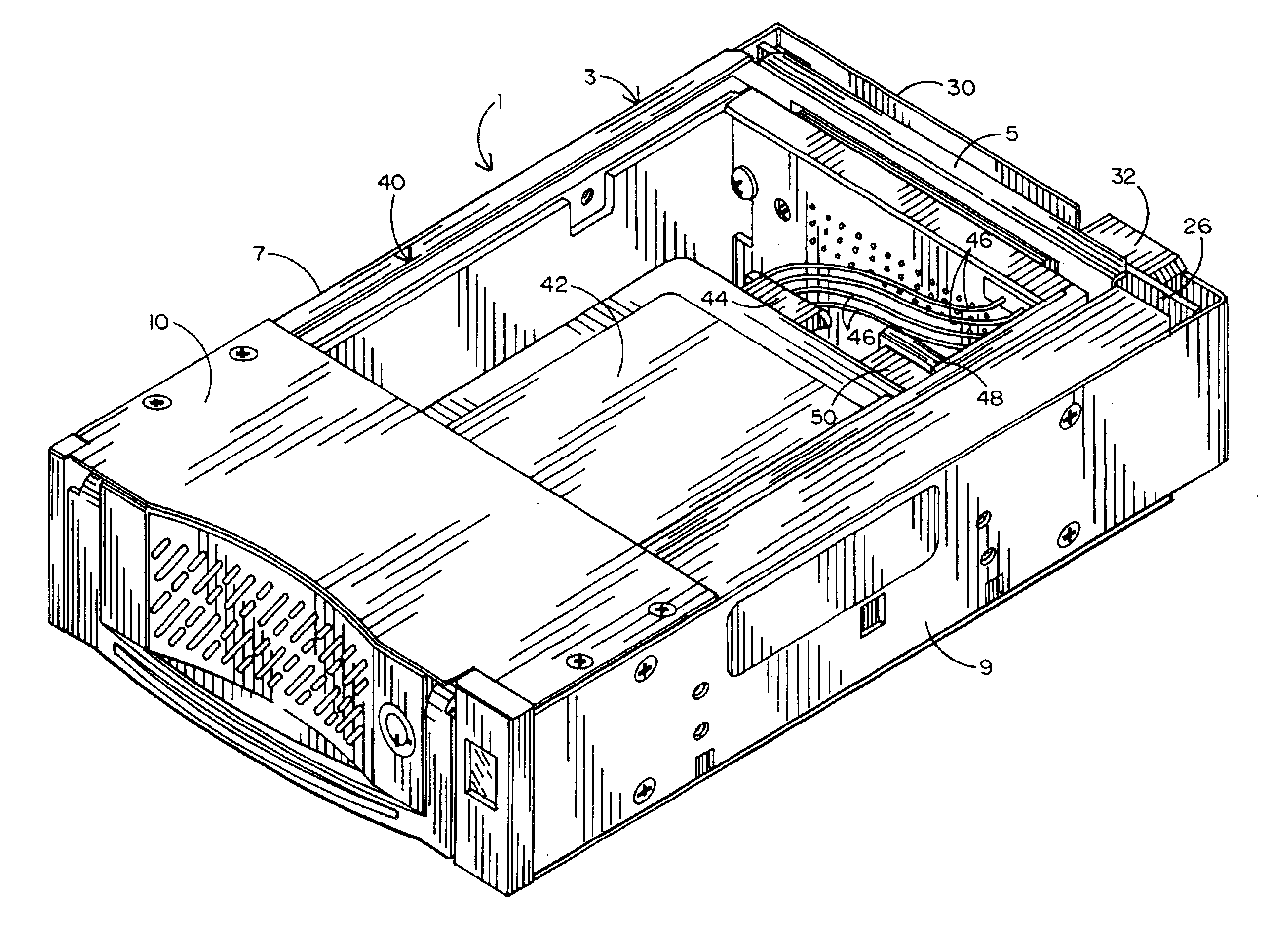
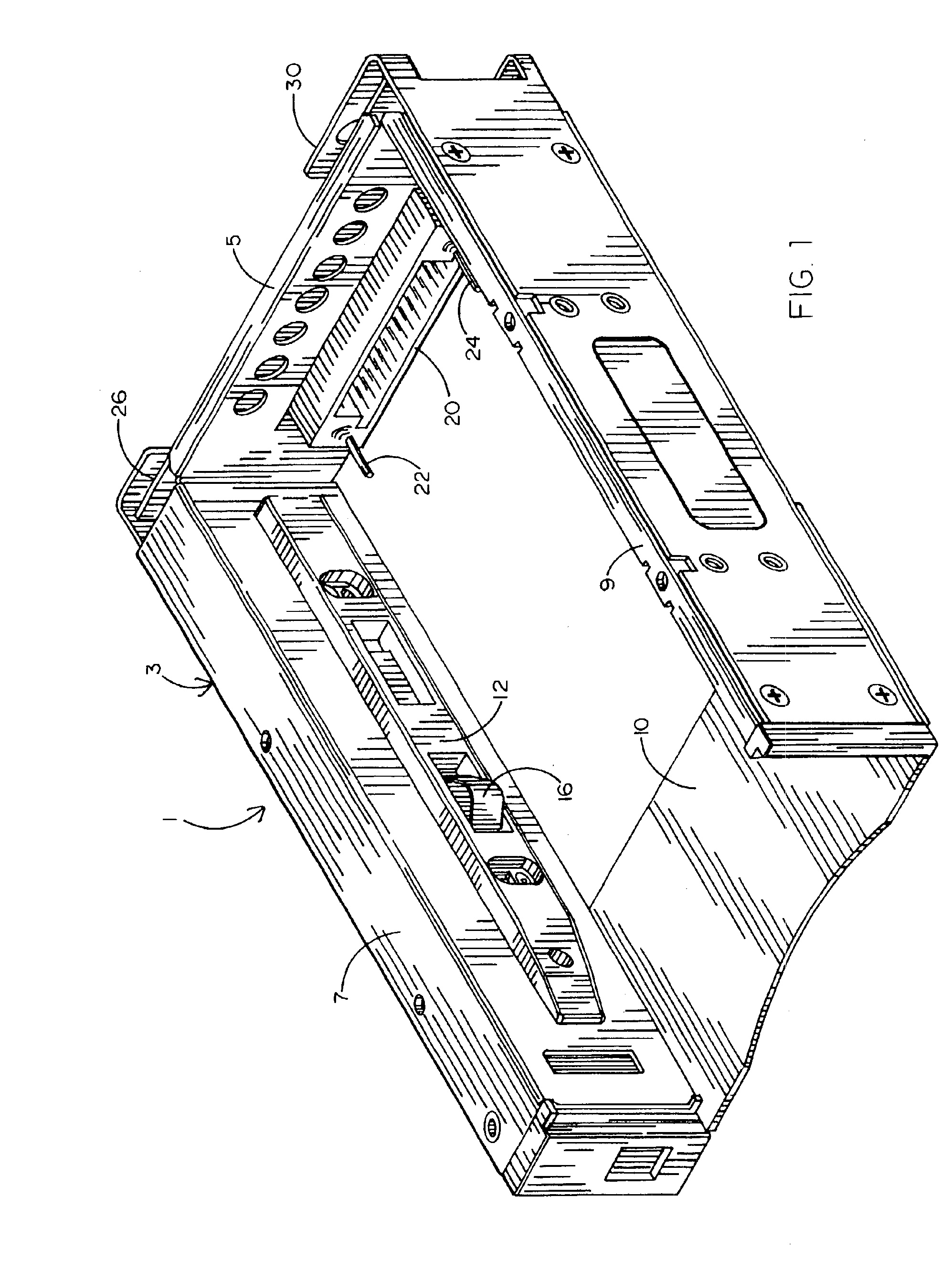
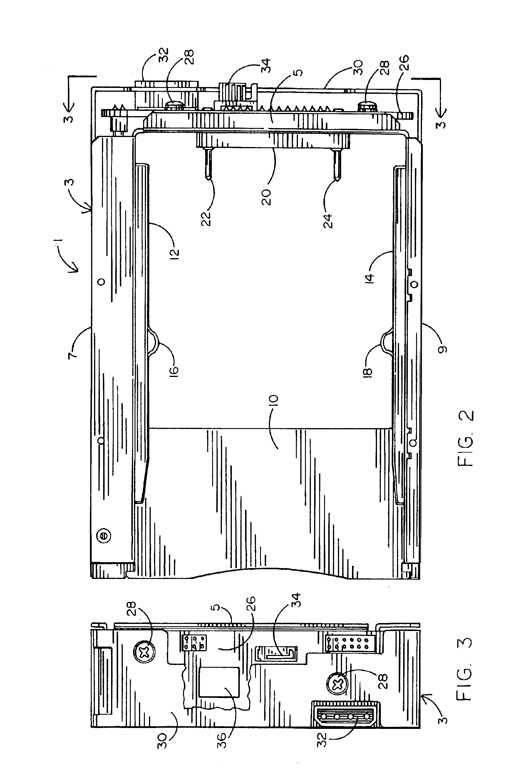
[0019]Referring initially to FIGS. 1-3 of the drawings, there is shown a universal receiving frame 1 according to a first embodiment of this invention for receiving a removable drive carrier (best shown in FIGS. 4 and 5) of the type in which either one of a serial or parallel connected computer drive is enclosed and transported. The universal receiving frame 1 has a generally U-shaped body 3 that is manufactured from metal and sized to receive and surround a conventional removable carrier. One or more universal receiving frames like that shown in FIG. 1 are typically stacked within respective drive bays of a chassis or storage enclosure in which a corresponding one or a plurality of remote portable computer drives and their removable carriers are housed. In this case, the chassis in which receiving frame 1 is located is separated from a host computer. By way of example, the portable computer drives that are enclosed by respective removable carriers and connected therein for either s...


PUM


Abstract

A universal receiving frame to be mounted in a drive bay of a chassis or storage enclosure that is interfaced with a host computer. The universal receiving frame is capable of interchangeably receiving different removable computer drive carriers having respective remote computer drives that are configured for parallel and serial operation. A printed circuit board is mounted on the back wall of the universal receiving frame in which an incoming removable drive carrier is slidably received. A suitable (e.g. a Serial ATA) interface and a serial-to-parallel bridge are located on the printed circuit board of the frame, whereby different removable carriers, regardless of drive configuration, can communicate with the chassis by way of the same receiving frame. In an alternate embodiment, which eliminates the universal receiving frame, the removable carriers are connected to one side of a backplane within the chassis and pull-out peripheral circuit boards are connected to the opposite side. A serial-to-parallel bridge is mounted on each of the removable carriers and a serial-to-serial or serial-to-parallel converter is mounted on each of the peripheral circuit boards.

Description

BACKGROUND OF THE INVENTION[0001]1. Field of the Invention[0002]This invention relates to receptacles by which different removable carriers having portable computer drives connected for either serial or parallel operation can be interchangeably received within the same chassis or storage enclosure so as to be interfaced with a host computer without having to make alterations to the computer drives or the chassis.[0003]2. Background Art[0004]With the advent of personal computers and workstations, it is often necessary to remove the medium on which computer data is stored. For example, it may be desirable to remove a storage medium so as to be carried to a different site and / or to a different computer system. It may also be desirable to remove the storage medium to a secure location when the computer data that is stored thereon is particularly sensitive or secret. To accomplish the foregoing, computer storage media (e.g. disc drives ) have been affixed to carriers that are removably r...

Claims


Application Information

Patent Timeline
IPC IPC(8): G06F1/18G11B33/12H05K7/14
CPCG06F1/18H05K7/1454G11B33/128G11B33/126
Inventor PAUL, DIETER G.TANG, CHOON-TAK
Owner CRU ACQUISITION GROUP
Learn More