Cache control device and manufacturing method thereof

a control device and cache technology, applied in the field of cache control devices and methods, can solve the problems of complex problems, difficult to completely flush cache data, and easy to occur bit errors

Inactive Publication Date: 2005-04-19
FUJITSU LTD
View PDF4 Cites 52 Cited by
  • Summary
  • Abstract
  • Description
  • Claims
  • Application Information

AI Technical Summary

Benefits of technology

[0019]Another object of the present invention is to provide a cache control device which makes degeneration of the cache possible in a multiprocessor chip by means of software or firmware in architectures that cannot issue transition instructions to a wait state so that the CPU inhibits the issuance of commands.
[0023]By means of the above, even if the CPU is a multiprocessor chip with an architecture that cannot issue a transition instruction to a wait state so that the CPU cores inhibit the issuing of commands by means of software or firmware, reliable execution of cache degeneration is possible.

Problems solved by technology

The cache 14 is a high integration memory device, therefore bit errors can easily occur due to alpha rays.
Specifically, if a one bit error occurs, it is reported to the software, and the software initiates degeneration control in response thereto.
However, in order for the software to do this, it is necessary for there to be a software command for suspending either one of the CPU cores so that it does not access the cache; if there is no such command, it is difficult to completely flush the cache data.
That is, as described above, where only the CPU 21 is changed, without the memory system 22 being changed, the software or firmware must be changed when the cache size, number of ways and cache control algorithm of the CPU are changed, creating complex problems.
However, in architecture which cannot issue a transition instruction to a wait state so that the CPU core inhibits commands, by means of software or firmware, since command inhibition control is not possible, as a result complete flushing of the cache data is difficult, hence the problem that degeneration of the cache is impossible.

Method used


Image

  • Cache control device and manufacturing method thereof
  • Cache control device and manufacturing method thereof
  • Cache control device and manufacturing method thereof

Examples


first embodiment

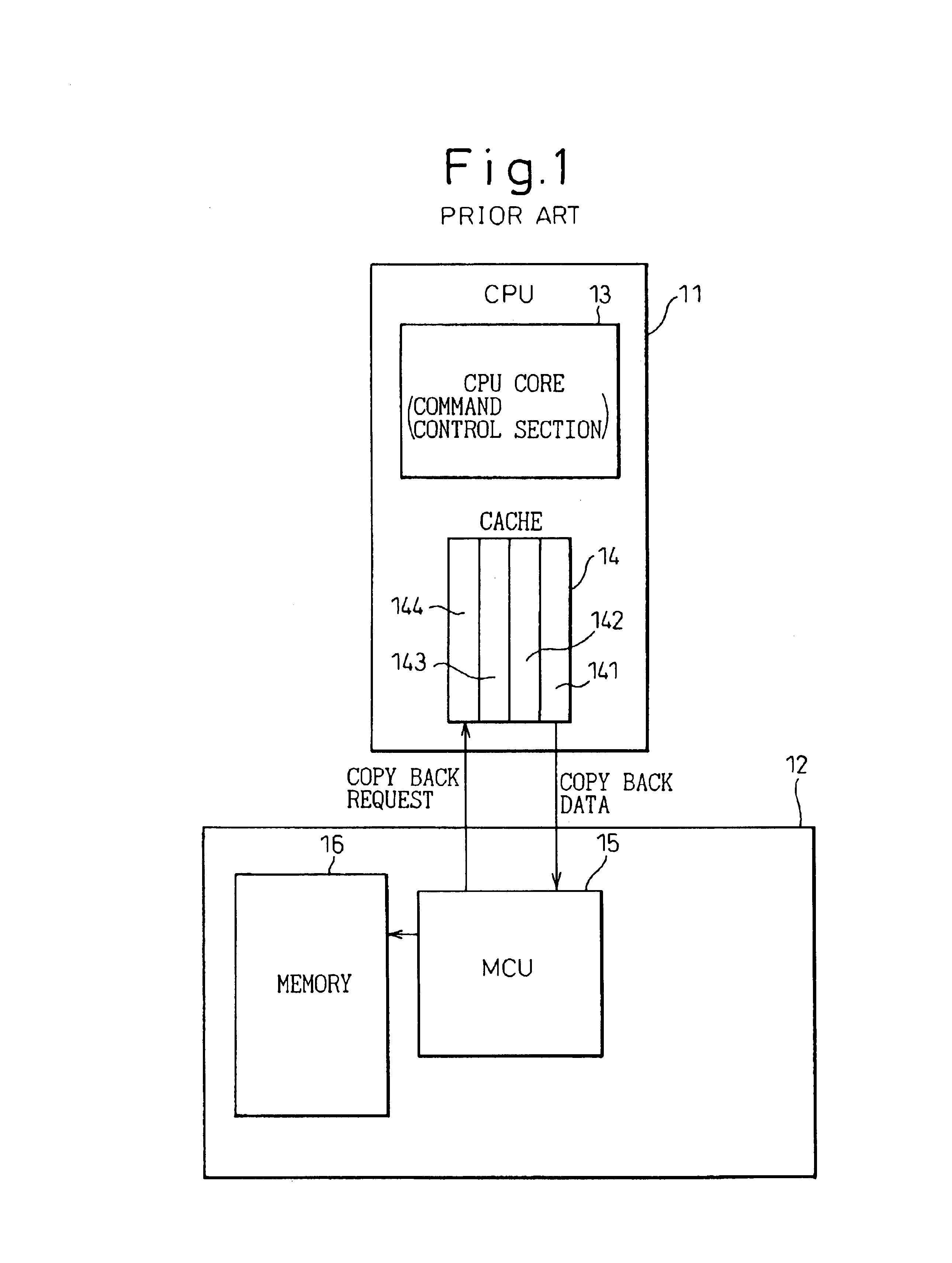
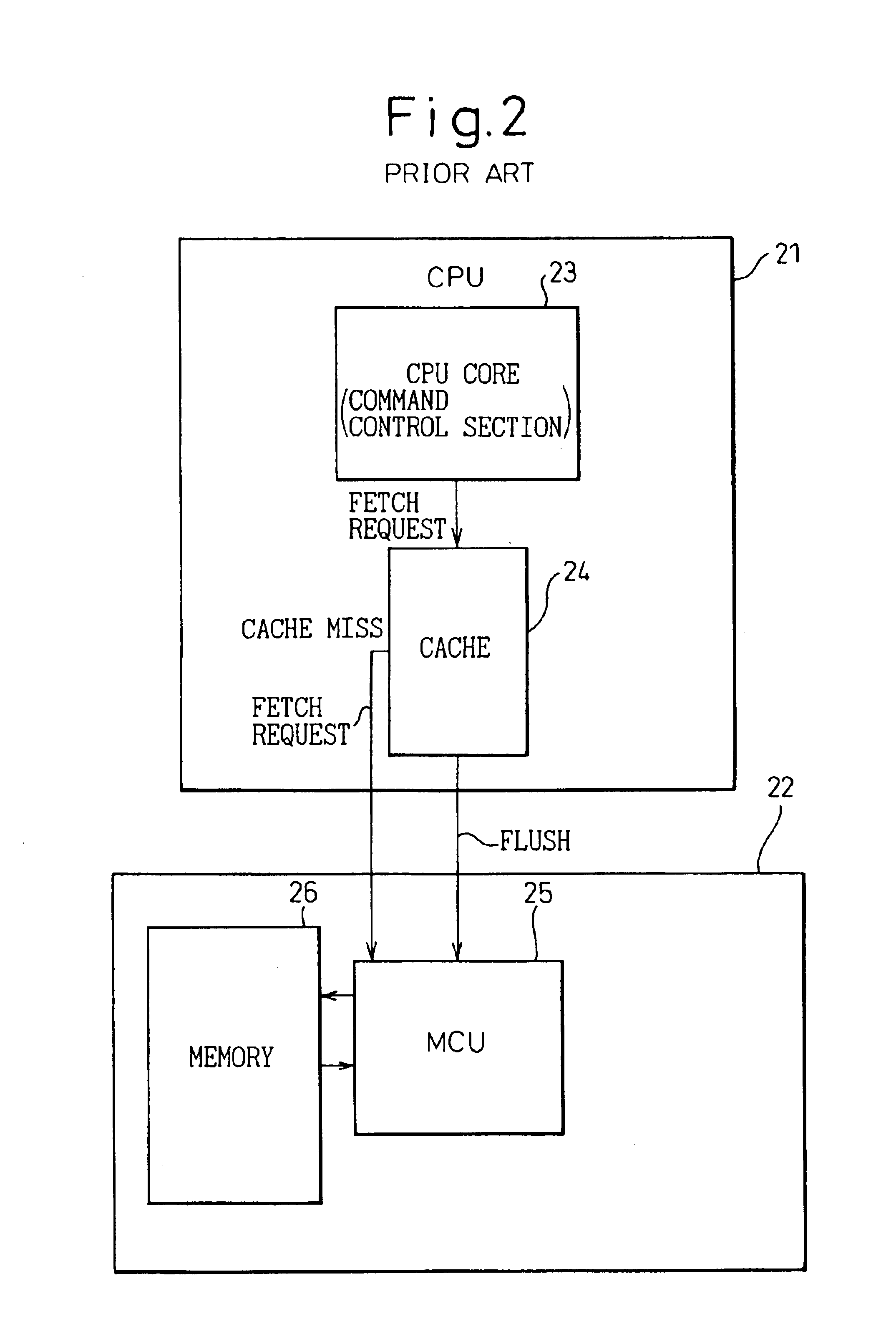
[0033]FIG. 4 is a block diagram showing part of the structure of a degeneration control device according to the present invention. In the drawing, the degeneration control device is part of an information processing device that includes a central processing unit (hereunder referred to as CPU) 41 and a memory system 42.

[0034]The CPU 41 includes a CPU core 43 which is the command control section and a cache 44. The cache 44 is designed as a set associative type comprising four ways 441 to 444 for example. The memory system 42 comprises a memory control unit (MCU) 45 and a memory 46.

[0035]In the present embodiment, degeneration control of the cache 44 is performed by hardware instead of software or firmware.

[0036]The operation of the present embodiment will be briefly explained next.

[0037]If a count value of a cache error frequency counter (not shown) exceeds a fixed number, a cache degeneration request is sent to the CPU core 43.

[0038]Once the degeneration request for the cache 44 is ...

second embodiment

[0059]FIG. 8 is a block diagram showing the structure of a degeneration control device according to the present invention. In the drawing, this degeneration control device is also part of a data processing device including a CPU 81 and memory system 82.

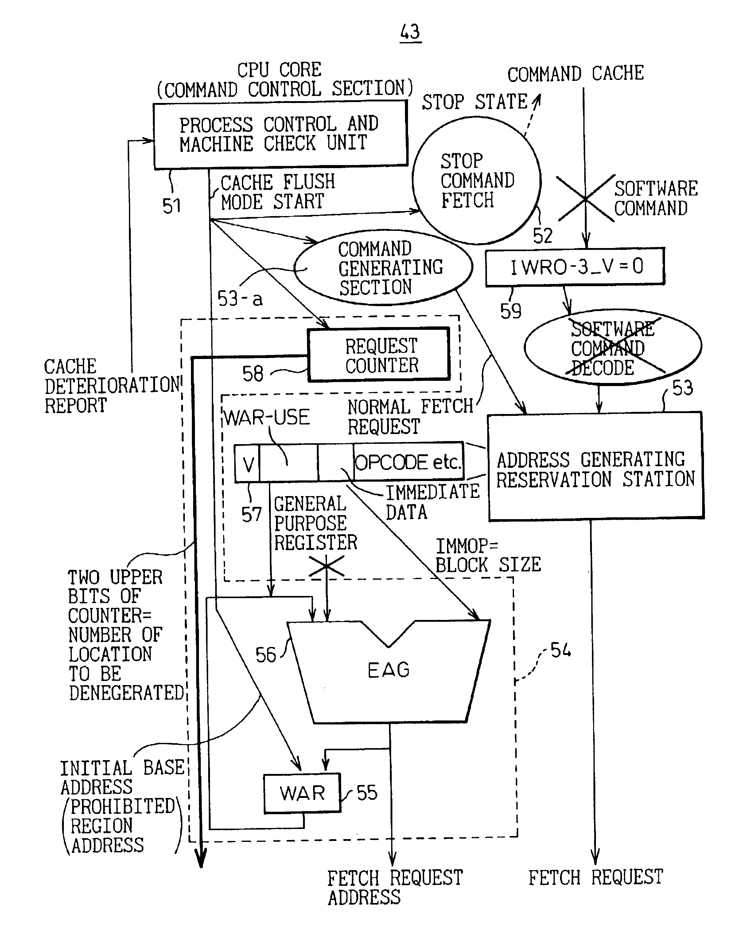
[0060]The CPU 81 is a multiprocessor chip comprising two CPU cores 83 and 84 and a cache 85, only one CPU core 83 of these two CPU cores comprising a command control section 51, software interrupt section 52, a command generating section 53a for generating fetch requests for flushing cache data, a degeneration flush address generating section 54, and a request counter 58 for specifying ways to be flushed.

[0061]In a system having this type of multiprocessor chip (CMP) structure, in this case where cache degeneration is performed by the CPU, the degeneration request is sent from the cache 85 to both of the CPU cores 83 and 84, and the CPU cores 83 and 84 enter a stop state. Also, only one CPU core 83 performs control as explained in the...


PUM


Abstract

A cache control device comprises a command control section 43 for receiving a cache deterioration report and generating a cache flush mode initiation signal which performs degeneration of the cache 44, a software interrupt section 52 for interrupting the supply of commands from software in response to the cache flush mode initiation signal, a command generating section 53a for generating fetch requests in which cache data flushing occurs to the cache in response to the cache flush mode initiation signal, an address generating section 54 for generating addresses for flushing the cache data in response to the cache flush mode initiation signal, and a request counter 58 for specifying ways at which flushing of the cache will be performed, whereby degeneration is possible where different CPUs are mounted in the system, or where a CMP micro architecture is employed, without the necessity of changing the system hardware or OS, or making additions to the computer architecture.

Description

BACKGROUND OF THE INVENTION[0001]The present invention relates to a cache control device and method for, in an information processing device having a cache, degenerating the cache by means of hardware.[0002]In a prior art cache control system, there are a method of performing degeneration by hardware and a method of performing degeneration by operating system software (OS).[0003]FIG. 1 is a block diagram showing a prior art main frame structure as an example of hardware control. In the drawing, the main frame comprises a central processing unit (hereafter referred to as a CPU) 11 and a memory system 12. The CPU 11 includes a CPU core 13 and a cache 14 which are the command control section. The cache 14 is designed as a four-way set associative cache comprising four cache ways 141 to 144. The memory system 12 is provided with a memory control unit (MCU) 15 and memory 16.[0004]The cache 14 is a high integration memory device, therefore bit errors can easily occur due to alpha rays. If...

Claims


Application Information

Patent Timeline
Patent Type & Authority Patents(United States)
IPC IPC(8): G06F12/08G06F12/16
CPCG06F12/0804
Inventor YOSHIDA, TOSHIO
Owner FUJITSU LTD
Why Eureka
Try Eureka