Quadrature compensation technique for vibrating gyroscopes

a compensation technique and vibrating gyroscope technology, applied in the field of vibrating gyroscopes, can solve problems such as substantial rate measurement errors, and achieve the effect of cancelling quadrature torqu

Inactive Publication Date: 2005-04-26
LITTON SYST INC +1
View PDF18 Cites 27 Cited by
  • Summary
  • Abstract
  • Description
  • Claims
  • Application Information

AI Technical Summary

Problems solved by technology

However, if the quadrature torque is large, as sometimes occurs, a small error in the phase of the feedback torque, at the dither frequency, will generate a substantial error in the rate measurement.

Method used


Image

  • Quadrature compensation technique for vibrating gyroscopes
  • Quadrature compensation technique for vibrating gyroscopes
  • Quadrature compensation technique for vibrating gyroscopes

Examples


Embodiment Construction

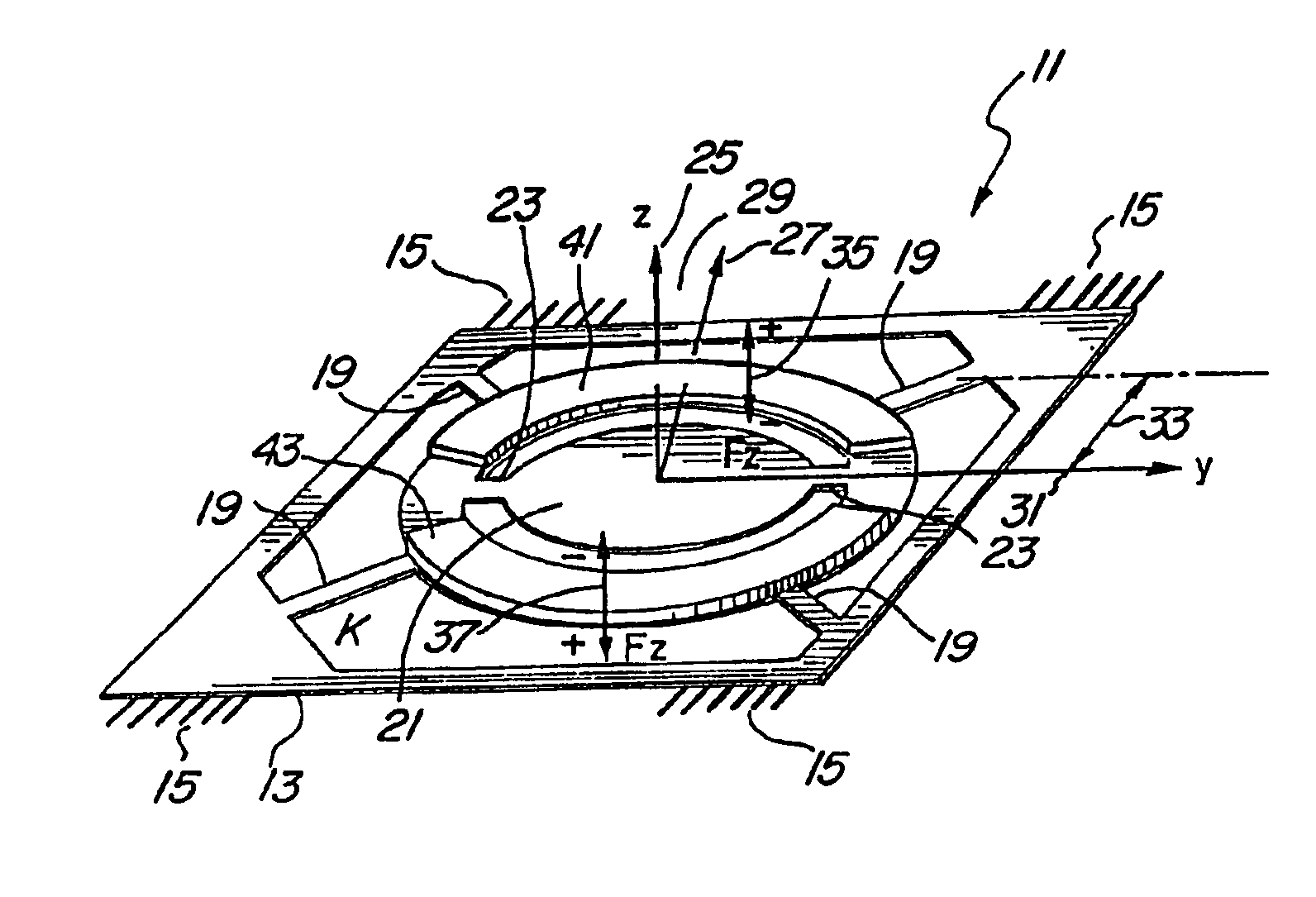
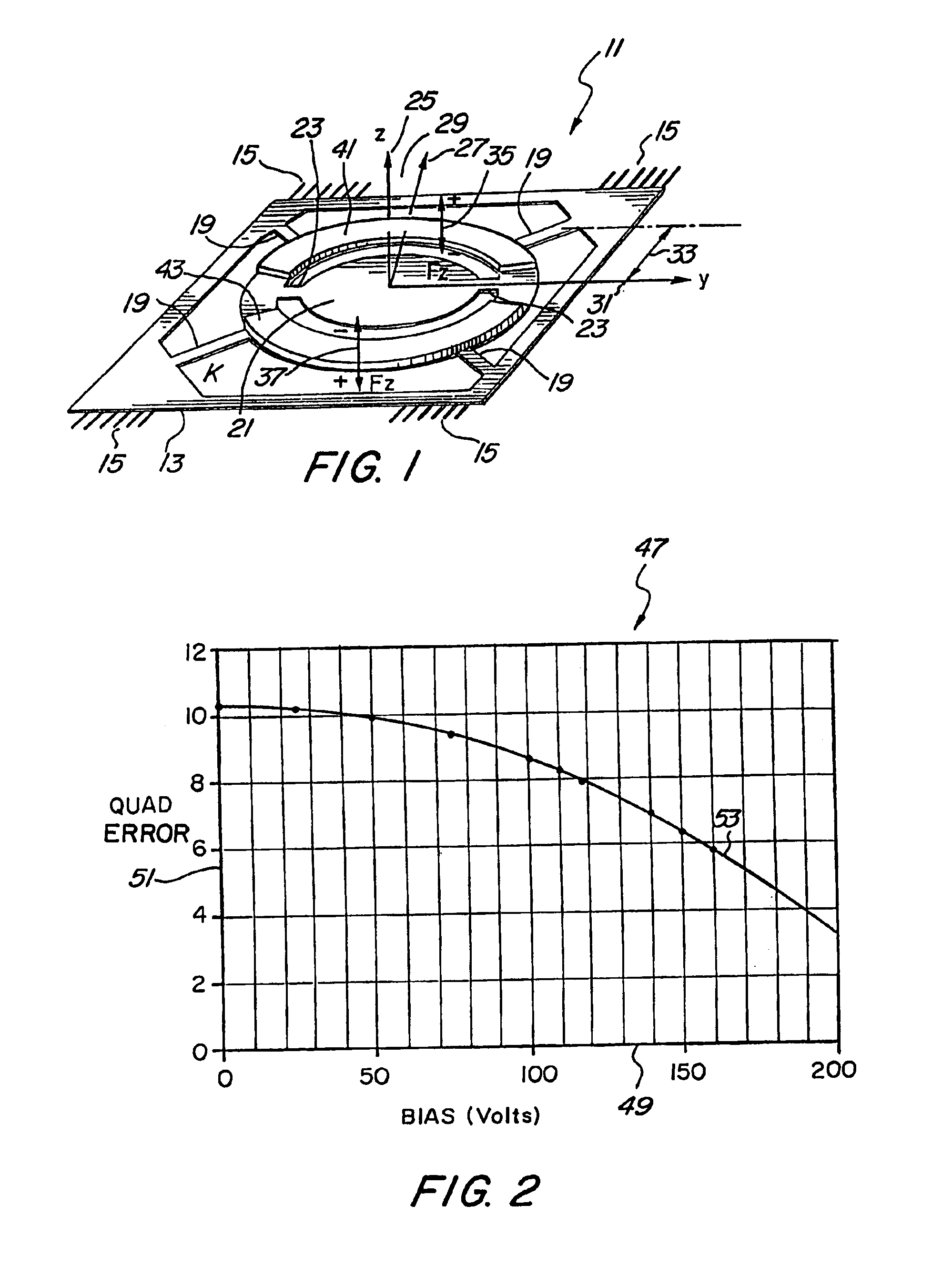
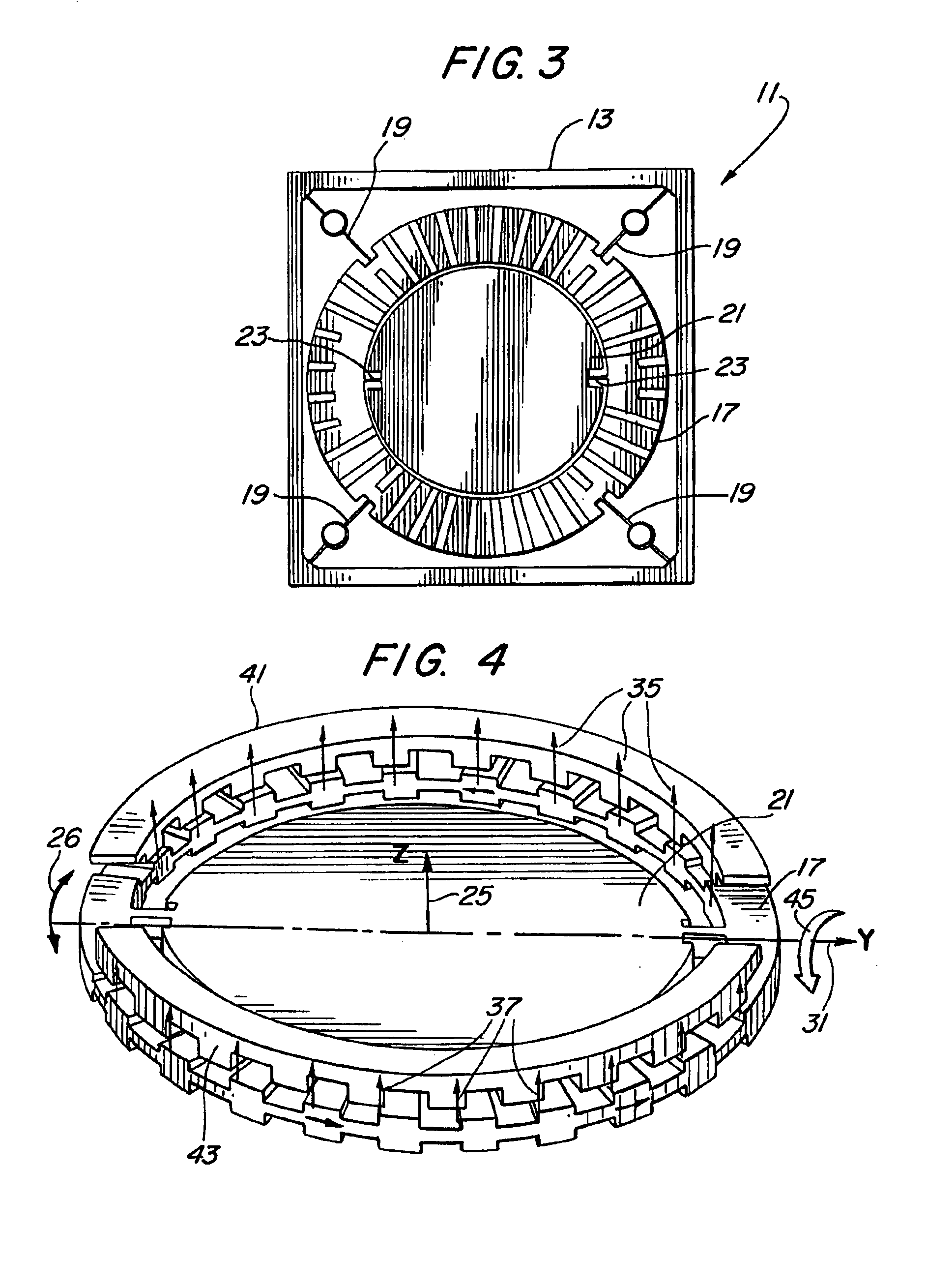
[0013]The construction of various forms of vibrating gyroscopes produced from silicon wafers is well known. U.S. Pat. No. 5,987,986 granted Nov. 23, 1999 to Stanley F. Wyse, Robert E. Stewart, and Samuel H. Fersht for Navigation Grade Micromachined Rotation Sensor System, and assigned to the same assignee as the present application, is one example. The entire disclosure of U.S. Pat. No. 5,987,986 is incorporated herein by reference as if fully set forth hereat.

[0014]Various techniques of nulling the quadrature error that is created in such gyroscope structures have been tried. One such technique is shown and described in an article entitled Surface Micromachined Z-Axis Vibratory Rate Gyroscope by William A. Clark, Roger T. Howe, and Roberto Horowitz presented at a Solid-State Sensor and Actuator Workshop in Hilton Head, S.C. on Jun. 2-6, 1996.

[0015]The technique proposed in the present application is different and is best illustrated by reference to FIGS. 1, 3 and 4 which shows in s...


PUM


Abstract

Quadrature error occurs in vibrating gyroscopes because of manufacturing flaws that permit the sensing element (proof mass) to oscillate about an axis that is not orthogonal to the output axis. This creates an oscillation about the output axis that has a component of the sensing element's vibration acceleration. This output axis oscillation, which is in phase with the driven acceleration of the sensing element, is called quadrature torque since it is ninety degrees out of phase with the angular rate induced acceleration. In order to eliminate this output axis oscillation, the present invention generates sinusoidal forces on the dither mass by applying dc voltages on the dither mass pickoff electrodes. These forces create a counter dither motion about the output axis that cancels the output axis oscillation generated by the non-orthogonal dither axis.

Description

CROSS REFERENCE TO RELATED APPLICATION[0001]This application is a division of application Ser. No. 10 / 127,165 filed Apr. 22, 2002 for Quadrature Compensation Technique for Vibrating Gyroscopes.BACKGROUND OF THE INVENTION[0002]1. Field of the Invention[0003]The present invention relates to an inertial instrument, and more specifically pertains to vibrating gyroscopes.[0004]2. Description of the Prior Art[0005]Gyroscopes are well known for use as sensors for sensing angular velocity acceleration which information is necessary for determining the location, direction, position, and velocity of moving vehicles, for example. Vibrating gyroscopes, while providing advantages in size and cost, have exhibited quadrature torque generated in the gyroscope output axis, apparently because the dither drive for such vibrating gyroscopes couples energy into the output axis as a result of the non-orthogonality between the dither axis and the output axis. This angular acceleration torque on the output...

Claims


Application Information

Patent Timeline
Patent Type & Authority Patents(United States)
IPC IPC(8): G01C19/56G01C19/5719
CPCG01C19/5719G01C19/56
Inventor WYSE, STANLEY F.
Owner LITTON SYST INC
Why Eureka
Try Eureka