Automatic diagnosing system for rolling bearing fault

A technology for automatic diagnosis and rolling bearings, applied in mechanical bearing testing, vibration testing, measuring devices, etc., can solve problems such as inability to qualitatively analyze bearings

Inactive Publication Date: 2006-08-30
LUOYANG BEARING SCI & TECH CO LTD
View PDF1 Cites 36 Cited by
  • Summary
  • Abstract
  • Description
  • Claims
  • Application Information

AI Technical Summary

Problems solved by technology

At present, when the acceleration type and speed type measurement of bearing vibration are carried out in the industry, the accele

Method used


Image

  • Automatic diagnosing system for rolling bearing fault
  • Automatic diagnosing system for rolling bearing fault
  • Automatic diagnosing system for rolling bearing fault

Examples


Embodiment Construction

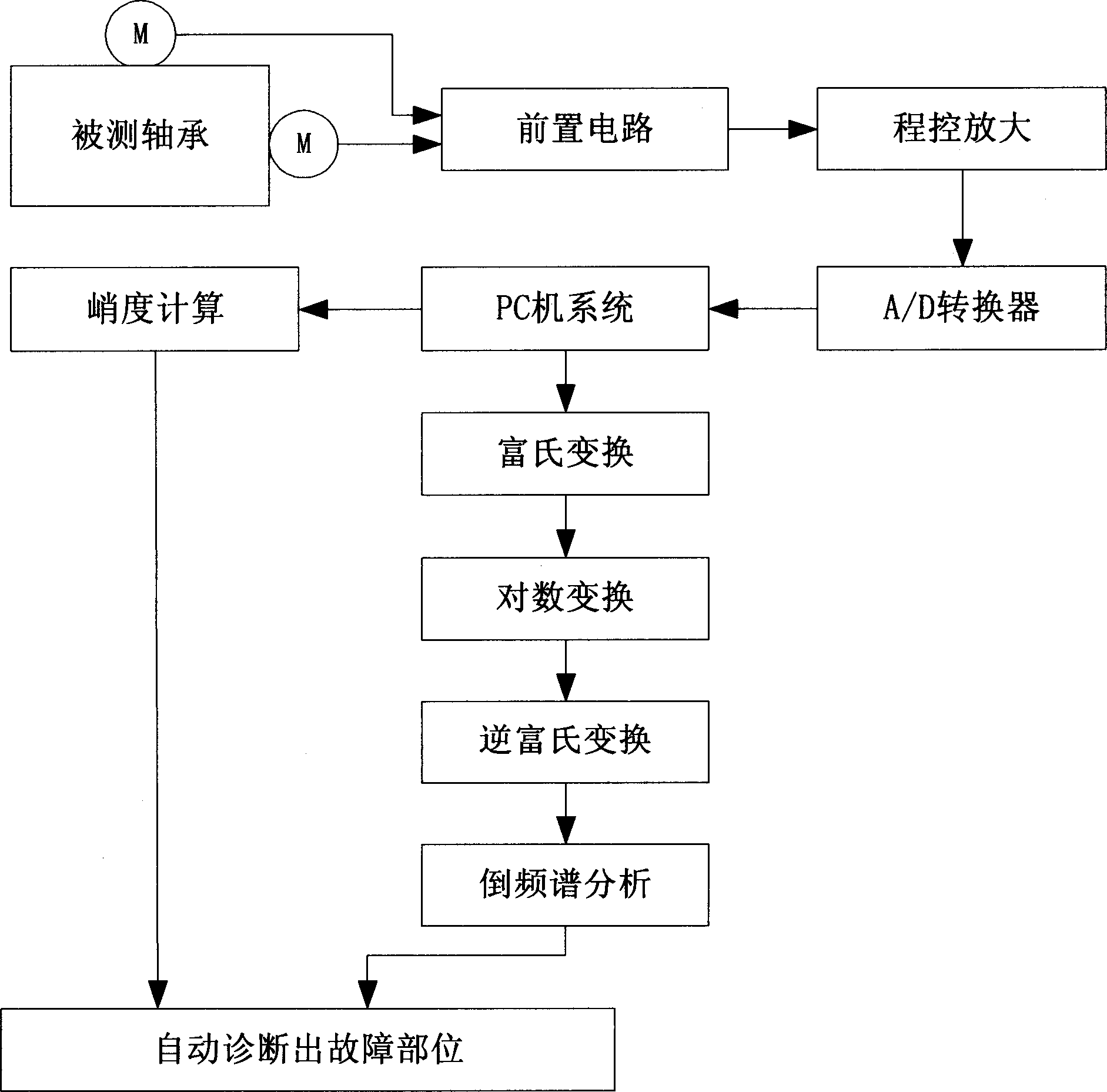
[0059] The invention provides a rolling bearing fault automatic diagnosis system, which utilizes bearing vibration test analysis and kurtosis analysis of bearing vibration, and through virtual instrument design and digital signal processing technology, the kurtosis value is automatically calculated by software, and then The spectrum analysis and comparison of the cepstrum can not only accurately test the vibration acceleration of the bearing, but also accurately test the vibration velocity of the bearing, and can perform multiple parameters such as time domain analysis, frequency domain analysis, and time-frequency domain joint analysis on the vibration of the bearing Quantitative and qualitative analysis, bearing abnormal sound and fault test analysis can also be carried out to achieve precise analysis of bearing vibration, and then compared with the fault characteristic frequency of the bearing or its frequency division and frequency multiplication characteristic values, it ca...


PUM


Abstract

The invention relates to a rolling bearing error auto diagnose system. It takes testing analysis and kurtosis analysis to the bearing vibration, and calculates the kurtosis by virtual device and DSP, analyzes and compares the spectral configuration to accurately measure the acceleration and speed of bearing vibration, and achieve accurate analysis to automatically judge the place of the error.

Description

Technical field: [0001] The invention relates to the technical field of bearing vibration testing and fault diagnosis, in particular to a rolling bearing fault automatic diagnosis system. Background technique: [0002] Rolling bearings are the most widely used general-purpose mechanical parts in various rotating machines. Many faults are related to the state of the bearings. The signals of rolling bearings are analyzed and processed to accurately identify the location of bearing faults, thereby improving bearing life and reliability. It provides a powerful means for vibration and noise reduction of the sex and roller bearings. [0003] Chinese invention patent CN1456872 discloses a diagnostic method for gear and rolling bearing faults. The time-delay correlation demodulation is performed on the signal. First, the autocorrelation analysis is performed on the measured vibration signal of the gear or rolling bearing, and the obtained autocorrelation signal Rx(τ) is time-delayed...

Claims


Application Information

Patent Timeline
IPC IPC(8): G01M7/02G01M13/04
Inventor 刘金秀任利珍朱孔敏
Owner LUOYANG BEARING SCI & TECH CO LTD
Why Eureka
Try Eureka