Inboard brake system for a straddle-type all-terrain vehicle

a technology of all-terrain vehicles and brake systems, which is applied in the direction of brake systems, brake disks or drums, brake lines, etc., can solve the problems of increasing exposing the components of the brake assembly, to damage from obstacles, and reducing the weight of the suspension, so as to reduce the weight carried, reduce the effect of componentry and reducing backlash

Inactive Publication Date: 2005-04-26
BOMBARDIER RECREATIONAL PROD INC
View PDF14 Cites 30 Cited by
  • Summary
  • Abstract
  • Description
  • Claims
  • Application Information

AI Technical Summary

Benefits of technology

[0012]It is another aspect of the invention to provide a brake system for an ATV that reduces weight carried by the suspension relative to prior art systems.
[0013]It is another aspect of the invention to provide a brake system for an ATV that has reduced componentry.
[0014]It is yet another aspect of the invention to provide a brake system for an ATV that reduces backlash within a drive assembly of the ATV.
[0017]It is another aspect of the invention to provide an ATV with a brake system that reduces weight carried by the suspension relative to prior art ATVs.
[0018]It is another aspect of the invention to provide an ATV with a brake system that has reduced componentry.
[0019]It is yet another aspect of the invention to provide an ATV with a brake system that reduces backlash within a drive assembly of the ATV.

Problems solved by technology

For example, mounting the brake assemblies to the front wheel assemblies exposes the components of the brake assemblies, such as the brake disks or drums, calipers, and brake lines, to damage from obstacles such as rocks and other debris.
Furthermore, the weight that is carried by the suspension is increased since the entirety of each brake assembly is mounted on the respective wheel assembly.
Strengthening the suspension system generally requires heavier and / or more expensive parts.
Furthermore, it may be more difficult to precisely tune or calibrate the suspension system, especially shocks and / or springs, to provide a comfortable ride.
These types of brake systems however usually lead to chain stretching, which may cause damaging backlash due to slack in the chain.
Upon braking, take-up of slack in the chain causes jarring of the ATV.
The jarring can cause fatigue wear of the rear axle components.
However, as with the similar front disk brake systems, these rear disk brake systems are prone to damage from debris and increase the sprung weight of the rear suspension.
Furthermore, four wheel drive-type all-terrain vehicles that have these types of brake systems are also subject to damaging backlash within the rear drive assembly, which typically includes a gear box.
Backlash is caused when braking power is transferred from, e.g., the rear brakes to the front of the vehicle through the rear drive assembly and drive line.
The jarring can cause excessive wear and fatiguing of the gears and result in damage to the rear drive assembly.
This type of brake system may decrease backlash somewhat, however is costly to manufacture.
This system is disadvantageous in that the brake system is exposed to the high heat conditions of the engine and transmission.
Prolonged exposure to high heat conditions is detrimental to brake pad and brake disk life and reduces braking effectiveness and efficiency.

Method used


Image

  • Inboard brake system for a straddle-type all-terrain vehicle
  • Inboard brake system for a straddle-type all-terrain vehicle
  • Inboard brake system for a straddle-type all-terrain vehicle

Examples


first embodiment

[0024]FIG. 3 is a detailed perspective view of the brake system of the present invention;

[0025]FIG. 4 is a side view of the brake system shown in FIG. 3;

[0026]FIG. 4A is a sectional view of a portion of the brake system taken along line 4A—4A in FIG. 4;

[0027]FIG. 5 is a front view of the first embodiment of the brake system shown in FIG. 3;

[0028]FIG. 6 is an exploded view of the brake system shown in FIG. 5;

second embodiment

[0029]FIG. 7 is a detailed perspective view of the present invention;

[0030]FIG. 8 is a front view of the brake system shown in FIG. 7;

[0031]FIG. 9 is a side view of the brake system shown in FIG. 8;

[0032]FIG. 10 is an exploded view of the brake system shown in FIG. 9; and

[0033]FIG. 11 is a top view of the second embodiment brake system shown in use with a different drive assembly.

DETAILED DESCRIPTION OF PREFERRED EMBODIMENTS

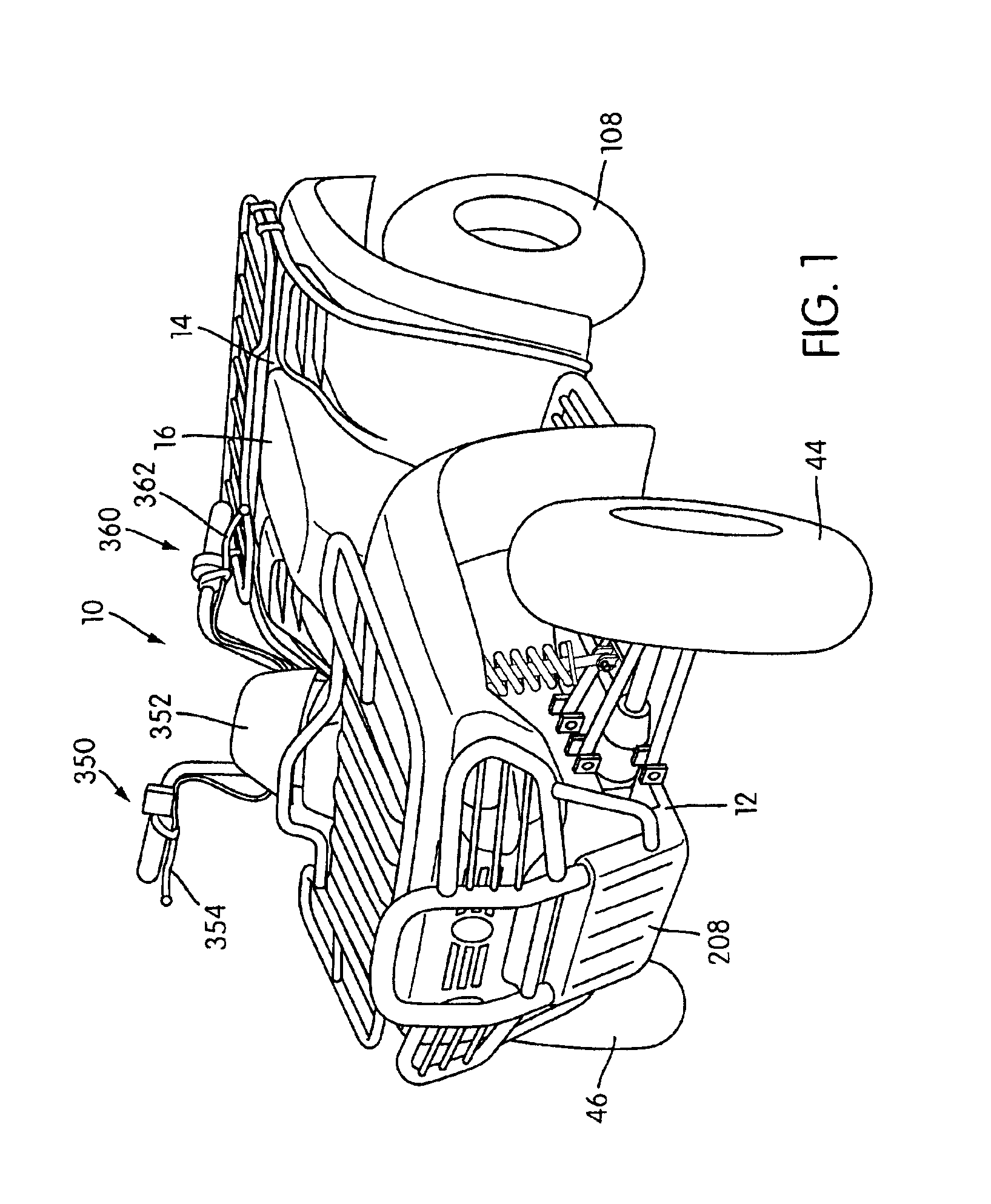
[0034]FIG. 1 shows an all-terrain vehicle (ATV) 10 equipped with a brake system of the present invention. The ATV 10 comprises a frame structure 12, which extends substantially the entire length of the ATV 10. A body portion 14 is disposed above and connected to the frame structure 12 and preferably includes a straddle-type seat 16 thereon.

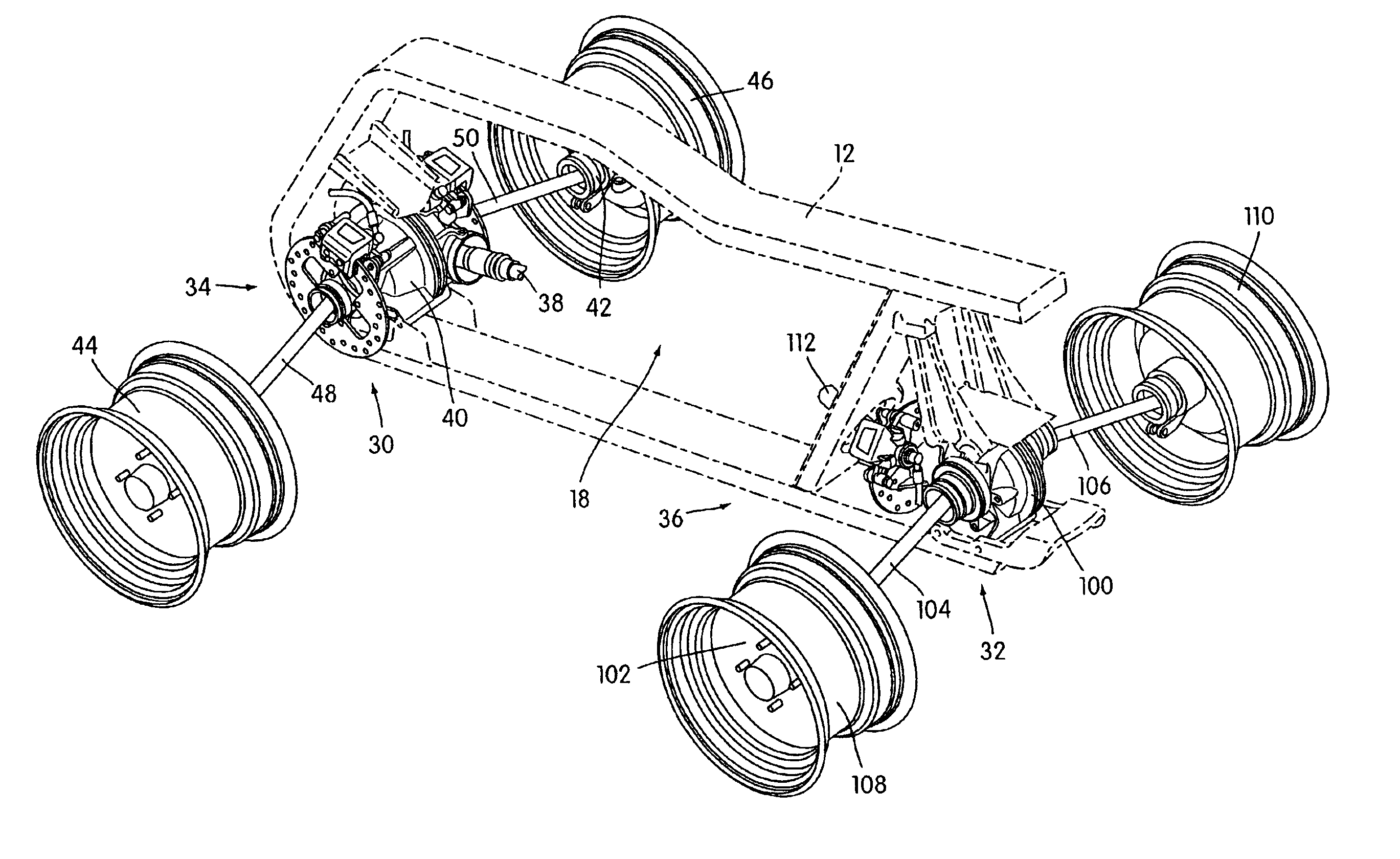
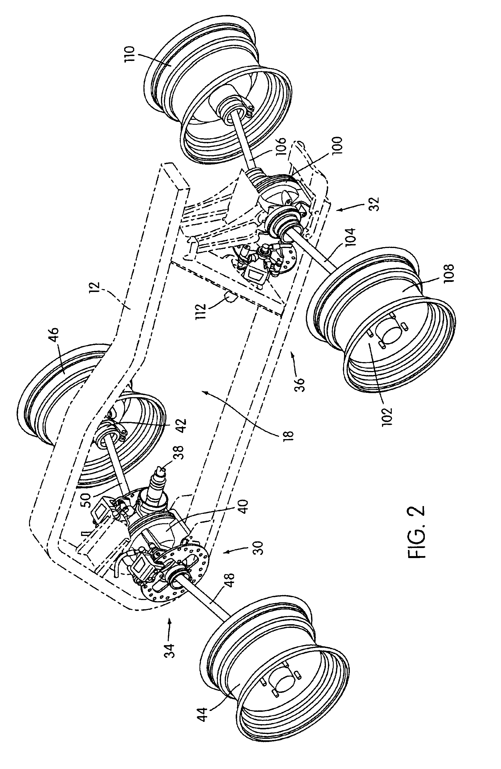
[0035]As shown in FIG. 2, frame structure 12 defines an engine-receiving opening, indicated at 18, within which a power unit, e.g., an engine (not shown), may be positioned. Preferably, the engine includes an integral transmiss...

embodiment 32

[0054]The embodiment 32 of the brake system illustrated in FIG. 2 is shown installed on a gear box and half-shaft type drive assembly. It is noted, however, that the brake system 32 may be used on either or both of a front and rear drive assembly. It is also noted that the brake system 32 is not limited to use with a gear box and half-shaft type drive assembly.

[0055]For example, FIG. 11 shows a drive assembly 150, which is a substantially rigid single axle type drive assembly. In particular, the drive assembly 150 includes a pair of tubular axle structures 152, 154 that are rigidly connected to opposite ends of an integral gear box 156. The gear box 156 is communicated with wheel assemblies 158, 160 via a respective pair of shaft elements 162, 164. An input portion 166 of the gear box 156 provides a flange structure 168, which is coupled to a caliper 170. It is noted that the flange structure 168 may be integral with the input portion 166 or that the flange structure 168 may be rigi...


PUM


Abstract

A brake system is provided for a straddle-type ATV. The brake system includes a brake caliper configured to mount to a gear box of the ATV and a brake disk configured to connect to a coupling member of the gear box coupled to a shaft and positioned in operative relation relative to the caliper. The brake system additionally includes a brake-actuating control mechanism in communication with the brake caliper. The brake-actuating control mechanism controls the brake caliper to provide selective frictional engagement between the brake caliper and the brake disk.

Description

CROSS-REFERENCE TO RELATED APPLICATIONS[0001]This application claims priority to U.S. Provisional Application Ser. No. 60 / 253,719, filed Nov. 29, 2000.BACKGROUND OF THE INVENTION[0002]1. Field of the Invention[0003]The present invention relates to a brake system for a vehicle and, more particularly, to an inboard brake system for a straddle-type all-terrain vehicle.[0004]2. Description of Related Art[0005]All-terrain vehicles (ATV's) generally utilize front and rear brake systems. Prior front brake systems have included disk or drum brake assemblies that are mounted to each front wheel assembly. For example, it is known in the art to mount a brake disk to the hub of each front wheel assembly that is engagable by a brake caliper. Each brake caliper is rigidly mounted to the upright structure of each wheel assembly, and is driven by a hydraulic or cable system that is actuated using a hydraulic or mechanical lever mounted on the handlebars. Additionally, it is known to mount a brake d...

Claims


Application Information

Patent Timeline
Patent Type & Authority Patents(United States)
IPC IPC(8): B60T1/00B60T1/06
CPCB60T1/062B60T1/065Y10S475/90Y10S180/908
Inventor MORIN, VINCENT
Owner BOMBARDIER RECREATIONAL PROD INC
Why Eureka
Try Eureka