Tool suspension device

a technology of tool suspension and tool body, which is applied in the direction of suspension devices, machine supports, other domestic objects, etc., can solve the problems of inconvenience for users and limit the versatility of conventional tool suspension devices, and achieve the effect of reducing disadvantages and/or obviating disadvantages

Inactive Publication Date: 2005-04-26
HUANG HSU JU
View PDF8 Cites 24 Cited by
  • Summary
  • Abstract
  • Description
  • Claims
  • Application Information

AI Technical Summary

Benefits of technology

[0006]The present invention is to mitigate and / or obviate the disadvantage of the conventional tool suspension device.

Problems solved by technology

Thus, after the fastening strap 12 is cut off, the conventional tool suspension device cannot be used to hang and position the ratchet wrench 14 any more, thereby causing inconvenience to the user, and thereby limiting the versatility of the conventional tool suspension device.

Method used


Image

  • Tool suspension device
  • Tool suspension device
  • Tool suspension device

Examples


Embodiment Construction

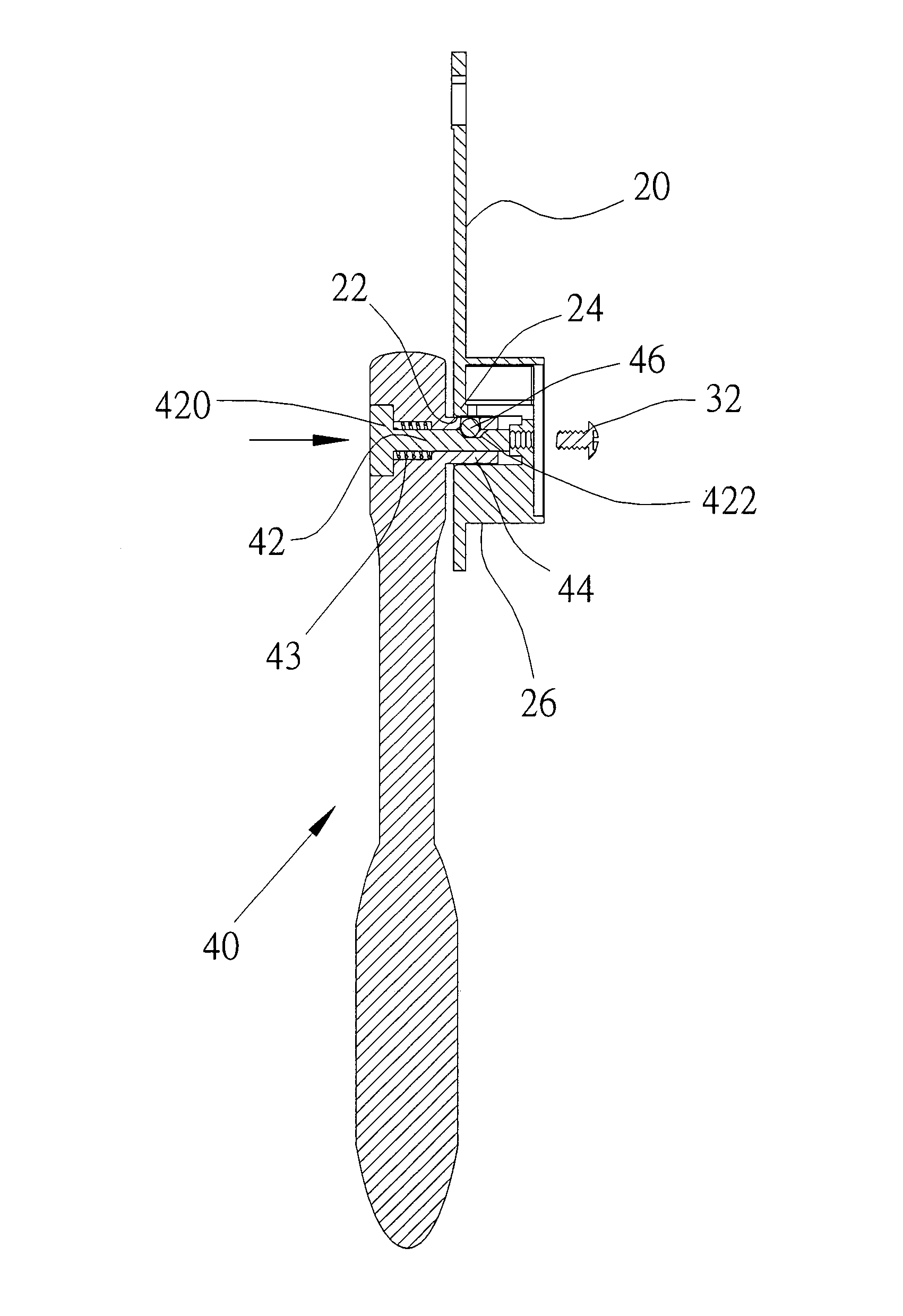
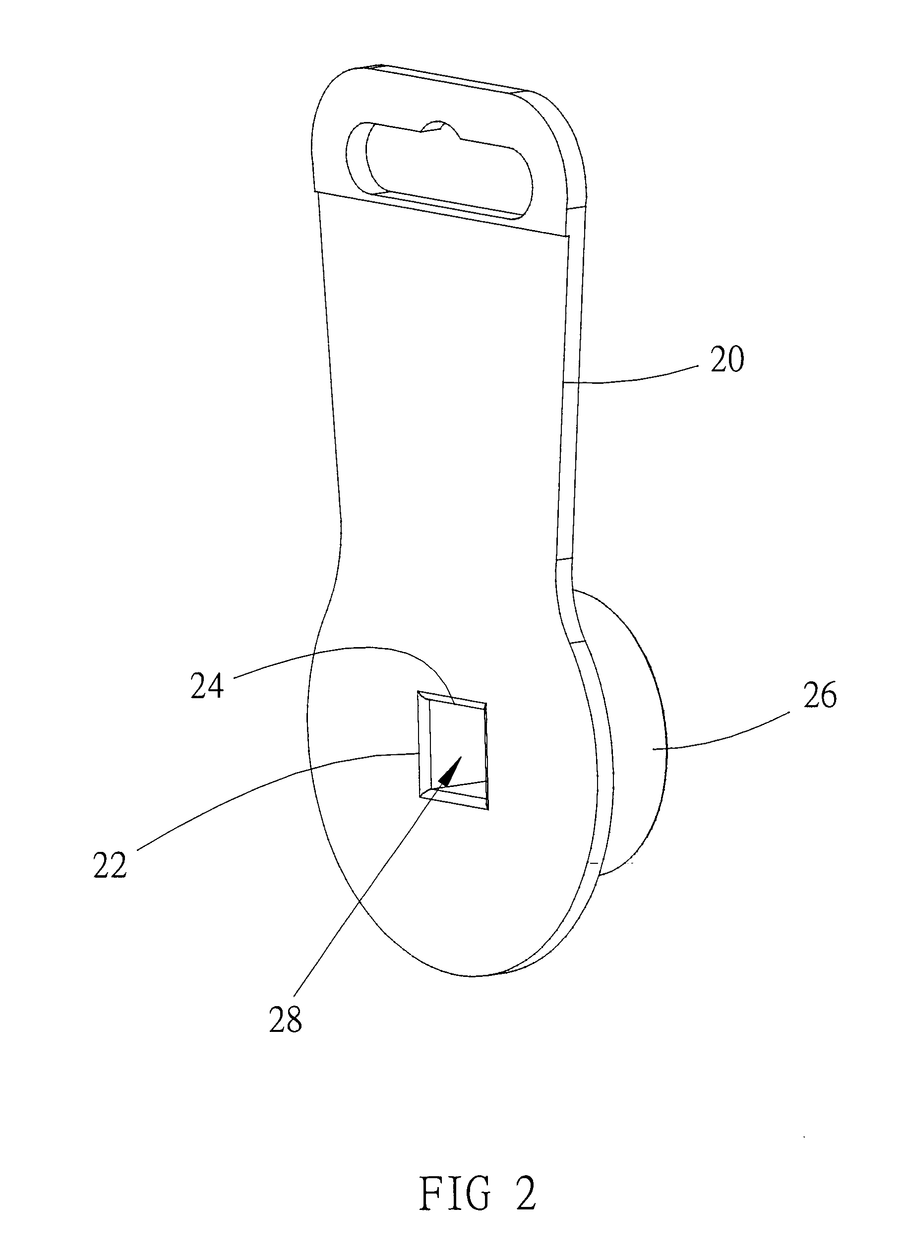
[0021]Referring to the drawings and initially to FIGS. 2–5, a tool suspension device in accordance with the preferred embodiment of the present invention comprises a main body 20 having a first side formed with a mounting hole 22 and a second side provided with a mounting portion 26 protruding outward therefrom. The mounting hole 22 of the main body 20 has a periphery formed with a catch edge 24. The mounting portion 26 of the main body 20 has an inside formed with a mounting space 28 communicating with the mounting hole 22. Preferably, the mounting space 28 is directed in an axial direction of the mounting portion 26 of the main body 20.

[0022]The tool suspension device further comprises a retaining member 32 mounted on an end face of the mounting portion 26 of the main body 20 and extended into the mounting space 28 of the mounting portion 26 of the main body 20. Preferably, the retaining member 32 is a screw. In practice, a ratchet wrench 40 is mounted on the tool suspension devi...


PUM


Abstract

A tool suspension device includes a main body having a first side formed with a mounting hole and a second side provided with a mounting portion. The mounting hole of the main body has a periphery formed with a catch edge. The mounting portion of the main body has an inside formed with a mounting space communicating with the mounting hole. Thus, the ratchet wrench can be mounted on and detached from the tool suspension device easily and conveniently, thereby facilitating the user using the ratchet wrench. In addition, the tool suspension device can be reused repeatedly.

Description

BACKGROUND OF THE INVENTION[0001]1. Field of the Invention[0002]The present invention relates to a tool suspension device, and more particularly to a tool suspension device that can be reused successively and repeatedly.[0003]2. Description of the Related Art[0004]A conventional tool suspension device in accordance with the prior art shown in FIG. 1 comprises a main body 10, and a fastening strap 12 mounted on the main body 10 for positioning a ratchet wrench 14. Thus, the conventional tool suspension device is placed on a wall or a display board to facilitate the consumers inspecting the ratchet wrench 14.[0005]However, it is necessary to cut off the fastening strap 12 to detach the ratchet wrench 14 from the main body 10. Thus, after the fastening strap 12 is cut off, the conventional tool suspension device cannot be used to hang and position the ratchet wrench 14 any more, thereby causing inconvenience to the user, and thereby limiting the versatility of the conventional tool sus...

Claims


Application Information

Patent Timeline
Patent Type & Authority Patents(United States)
IPC IPC(8): A47F5/00B65D73/00
CPCB65D73/0064A47F5/0006
Inventor HUANG, HSU JU
Owner HUANG HSU JU
Why Eureka
Try Eureka