
Perspective correction for preview area of panoramic digital camera

a panoramic digital camera and preview area technology, applied in the field of image processing, can solve the problems of wasting memory in the digital camera with redundant information, difficult to properly overlap a region between two adjacent frames of a panoramic image, and not without their shortcomings

Inactive Publication Date: 2005-04-26
SONIC SOLUTIONS LLC +1
View PDF9 Cites 89 Cited by
  • Summary
  • Abstract
  • Description
  • Claims
  • Application Information

AI Technical Summary

Benefits of technology

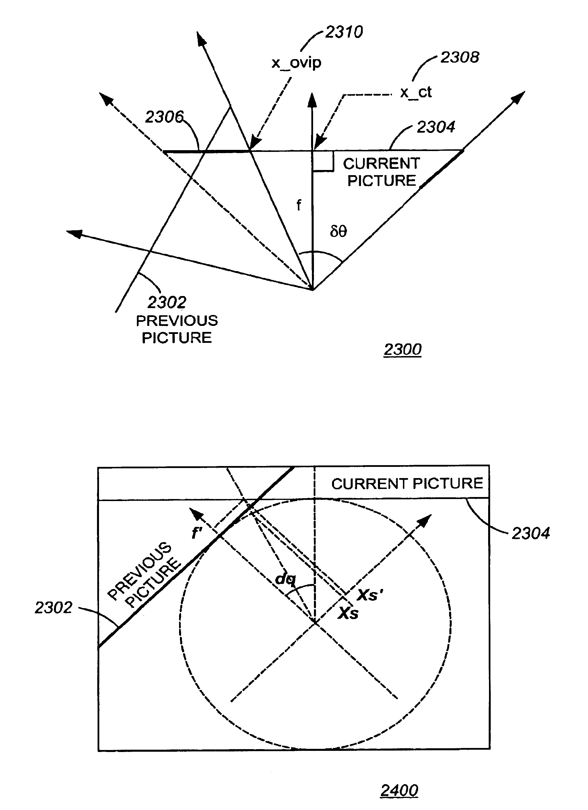
[0023]A device as part of a digital camera for image capturing at least two perspective images at a constant focal length from the digital camera, where both images share a common edge portion for creating a panoramic image. The device comprising: an input for receiving a current image which is updated in real time when a digital image capture mechanism coupled to the input is repositioned. The device further includes a preview generator for warping or mathematically adjusting perspective of a portion of a stored previous image so as to generate an overlap portion for optimal alignment by a user of the overlap portion to the current image therewith. The warped overlap portion of the stored previous image along with the current image is presented to a viewfinder.

Problems solved by technology

Although these techniques are useful, they are not without their shortcomings.
Another shortcoming of the current panoramic cameras is how difficult it is to properly overlap a region between two adjacent frames of a panoramic image.
Too much overlap results in wasting memory in the digital camera with redundant information.
Another shortcoming with current panoramic cameras is their inability to guide the user where the correct edge overlap is required for creating a panoramic picture alignment from two or more images.
Problems at the boundaries of two images include color distortion, perspective distortion, pixel adjacency and skipped pixels at the edges when joining two or more images.
Another shortcoming of the current panoramic cameras is their inability to integrate these mechanisms with other products.
The bulk, expense, and complication make these designs difficult to integrate.
Another shortcoming is the inability to easily capture two or more images to create a panoramic scene without the need for expensive computational resources in the camera and without the need for expensive position sensors.
The expense and space required for two buffers to coordinate transformations is undesirable.
This will produce a great loss of vertical resolution.
Many times, the added expense, the additional weight and the additional size of the electronic circuitry makes the camera unwieldy to carry and operate.
Moreover, the additional electronic circuitry makes the camera more expensive to manufacture.

Method used


Image

  • Perspective correction for preview area of panoramic digital camera
  • Perspective correction for preview area of panoramic digital camera
  • Perspective correction for preview area of panoramic digital camera

Examples


Embodiment Construction

[0080]However, it should be understood that these embodiments are only examples of the many advantageous uses of the innovative teachings herein. In general, statements made in the specification of the present application do not necessarily limit any of the various claimed inventions. Moreover, some statements may apply to some inventive features but not to others. In general, unless otherwise indicated, singular elements may be in the plural and visa versa with no loss of generality.

1. Glossary of Terms Used in this Disclosure

[0081]Actual Next Picture—the picture that is actually captured as the next addition to the set of pictures constituting the Panorama.

[0082]Bottom-to-Top Vertical Panorama—a Panorama captured by taking a set of pictures by rotating the camera up (from bottom to top) between each capture, with as little horizontal displacement as possible.

[0083]Current Buffer—a cylindrically warped version of the current picture.

[0084]Current Picture / Current View / Current Frame—...


PUM


Abstract

A device for creating a panoramic image from a plurality of images taken by a digital camera. The device comprising: an input for receiving a current image which is updated in real time when a digital image capture mechanism coupled to the input is repositioned. The device further includes a preview generator for warping or mathematically adjusting perspective of a portion of a stored previous image so as to generate an overlap portion for optimal alignment by a user of the overlap portion to the current image therewith. The warped overlap portion of the stored previous image along with the current image is presented to a viewfinder. In an alternate embodiment, a method and computer readable medium corresponding to the above system is described.

Description

CROSS-REFERENCE TO RELATED APPLICATIONS[0001]This application relates to technology similar to U.S. patent applications identified by Ser. No. 09 / 477,037, 99-RB-106 Ser. No. 09 / 477,036 now U.S. Pat. No. 6,677,981, 99-RB-107 Ser. No. 09 / 476,652 now U.S. Pat. No. 6,456,323,99-RB-123 Ser. No. 09 / 477,118 now U.S. Pat. No. 6,618,511, and 99-RB-167 Ser. No. 09 / 477,117 now U.S. Pat. No. 6,717,608, all being filed concurrently herewith and commonly assigned herewith to STMicroelectronics Inc. and which are hereby incorporated by reference in their entirety hereinto.PARTIAL WAIVER OF COPYRIGHT[0002]All of the material in this patent application is subject to copyright protection under the copyright laws of the United States and of other countries. As of the first effective filing date of the present application, this material is protected as unpublished material.[0003]However, permission to copy this material is hereby granted to the extent that the copyright owner has no objection to the fa...

Claims


Application Information

Patent Timeline
Patent Type & Authority Patents(United States)
IPC IPC(8): G06T3/40H04N5/232
CPCG06T3/4038H04N5/23293H04N5/23238H04N23/698H04N23/632
Inventor MANCUSO, MASSIMOLUSINCHI, EMMANUELTEO, PATRICK CHENG-SAN
Owner SONIC SOLUTIONS LLC
Learn More