Printing apparatus and method capable of flexibly controlling response signal
a technology of response signal and printing apparatus, which is applied in the direction of digital output to print units, instruments, visual presentations, etc., can solve problems such as degraded throughput, and achieve the effect of increasing data transmission speed
- Summary
- Abstract
- Description
- Claims
- Application Information
AI Technical Summary
Benefits of technology
Problems solved by technology
Method used
Image

Examples
first embodiment
(First Embodiment)
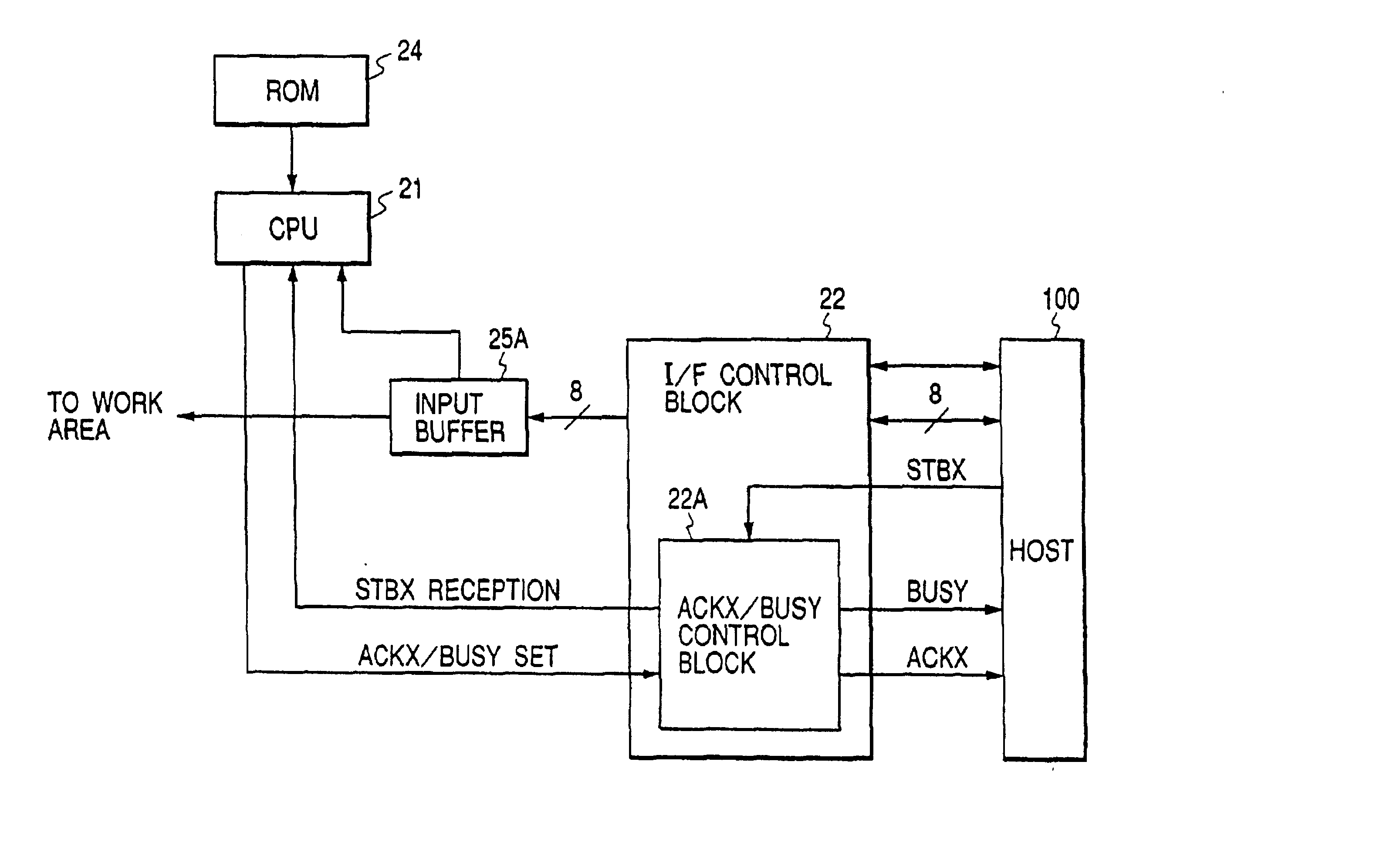
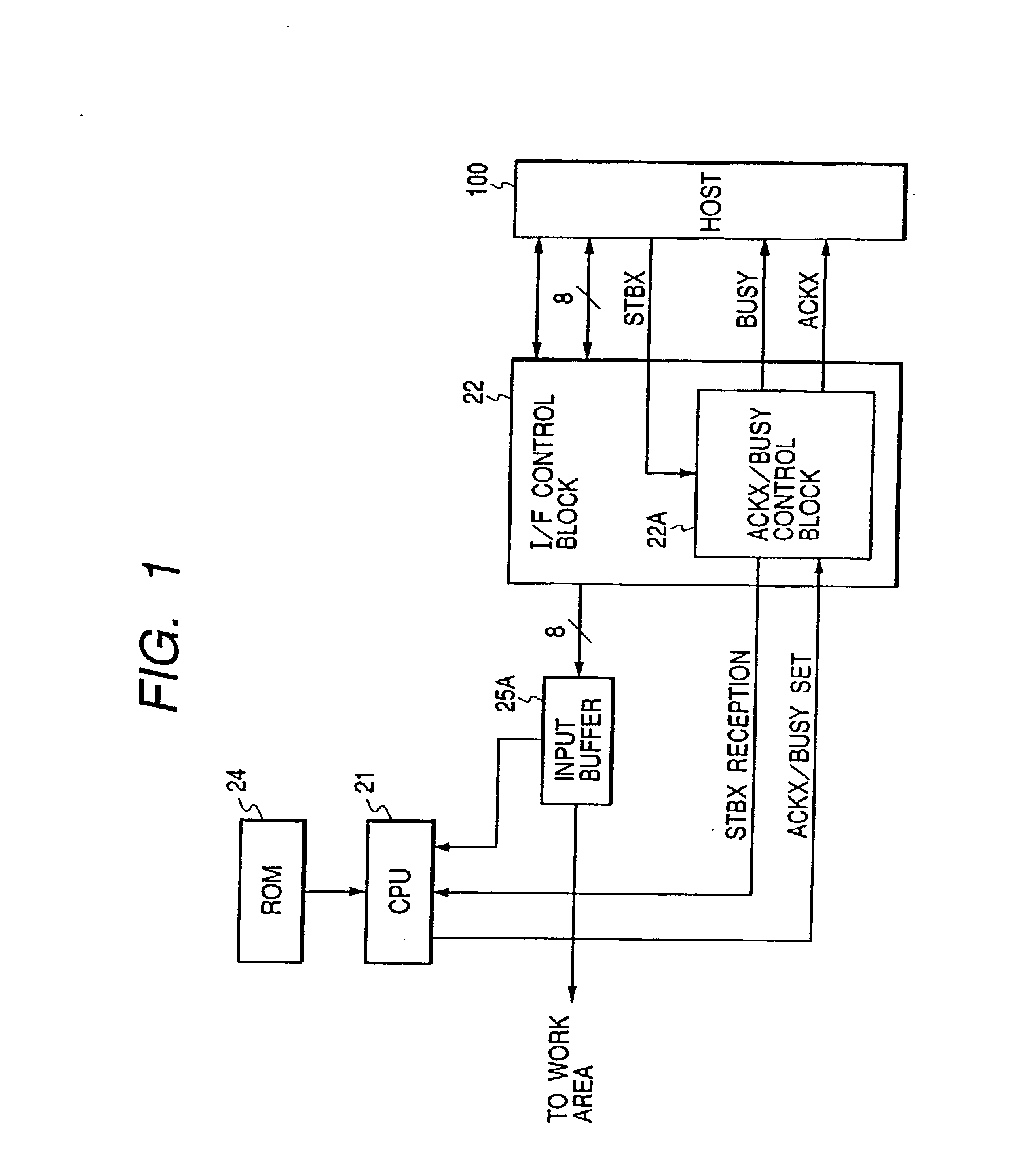
[0033]FIG. 1 is a block diagram briefly showing a main part or control system of an ink jet printer and a host apparatus according to an embodiment of the invention. The main part or control system of the ink jet printer is constituted of a CPU 21, an interface (I / F) control block 22, a ROM (program memory) 24, and a reception buffer 25A of a working memory 25 (refer to FIG. 3). The ink jet printer is connected via the I / F control block to the host computer.
[0034]The operation of each component of the ink jet printer will be described. CPU 21 controls each component of the ink jet printer in accordance with a program stored in ROM 24. The I / F control block 22 receives data transmitted from the host apparatus 100 and transfers the received data to the reception buffer 25A to be temporarily loaded therein. The I / F control block 22 has an ACKX / BUSY signal control block 22A.
[0035]The ACKX / BUSY signal control block 22A receives an STBX signal transmitted from the host a...
second embodiment
(Second Embodiment)
[0057]Similar to the first embodiment, the main part or control system of an ink jet printer according to the second embodiment is constituted of a CPU 21, an interface (I / F) control block 22, a ROM 24, and a reception buffer 25A of a working memory 25 (refer to FIG. 1).
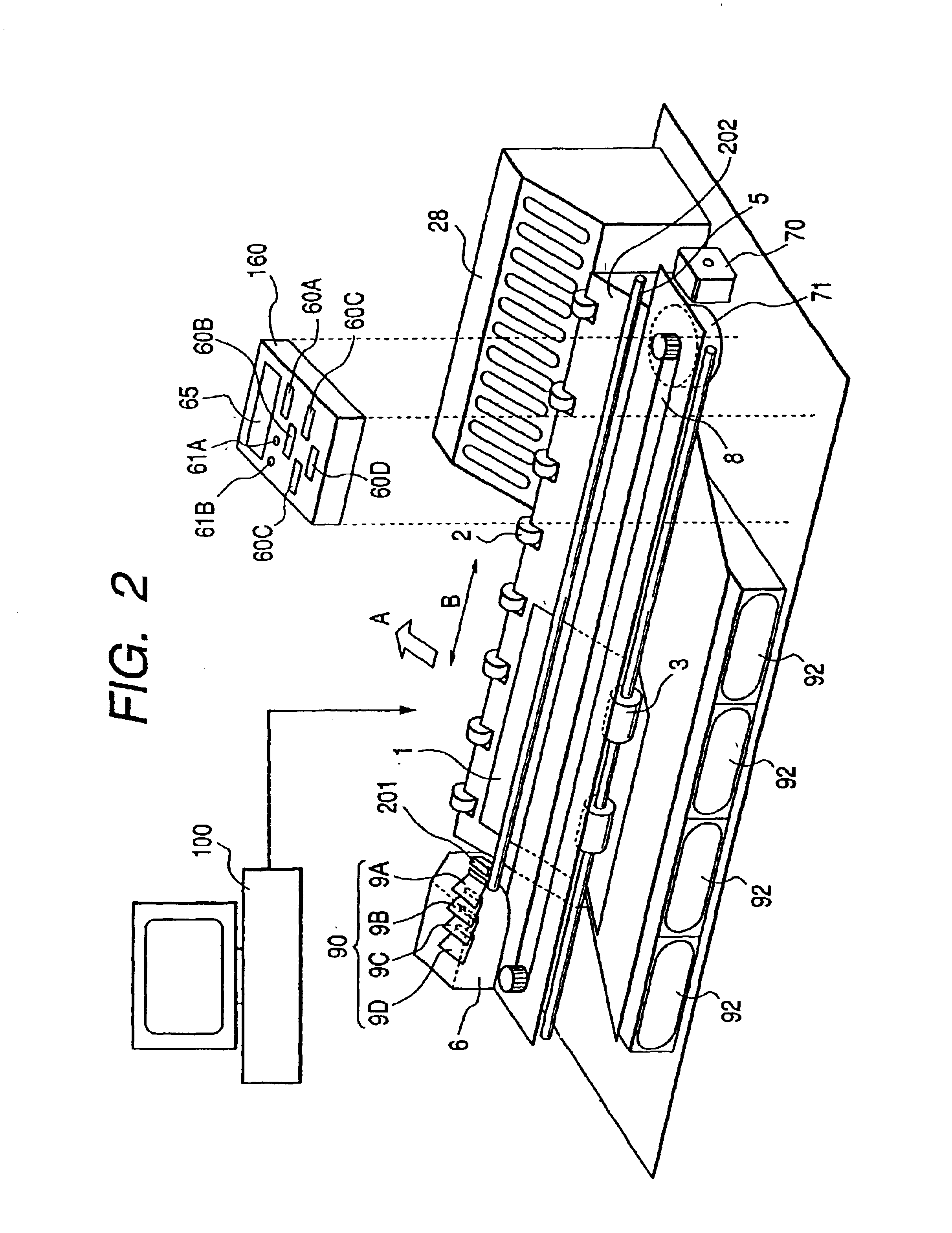
[0058]Similar to the first embodiment, the ink jet printer of the second embodiment has, in its main frame, transport rollers 2 and 3, a guide shaft 5, a carriage 6, a belt 8, a sheet feed motor 70, a carriage motor 71, a print head unit 90, an ink cartridge 92, an operation panel 160, and the like (refer to FIG. 2).
[0059]Similar to the first embodiment, the control system and the structure of each mechanical unit of the ink jet printer of the second embodiment, are constituted of CPU 21, data memory 23, program memory 24, working memory 25, power supply circuit 28, print head control circuit 29, black print head 9A, cyan print head 9B, magenta print head 9C, yellow print head 9D, I / F control block...
third embodiment
(Third Embodiment)
[0070]FIG. 11 is a block diagram showing the outline structure of a data processing system using a printer according to the third embodiment of the invention. This data processing system has a host computer 100 and a printer 200.
[0071]The host computer 100 is constituted of a data processing unit 110 and an interface unit 120. The data processing unit 110 has a CPU 111, a ROM 112, and a RAM 113. The interface unit 120 has an output buffer 121, an STBX generator 122, and a BUSY / ACKX detector 123. CPU 111 of the data processing unit 110 performs various data processing in accordance with a system program stored in ROM 112 and application programs and the like stored in an unrepresented hard disk.
[0072]The interface unit 120 conforms with the Centronics interface. The output buffer 121 of the interface unit 120 is used for temporarily storing print data processed by CPU 111 when a print command is issued or in other cases. The STBX generator 122 generates an STBX sign...
PUM
 Abstract
Description
Claims
Application Information
 - R&D Engineer
- R&D Manager
- IP Professional
- Industry Leading Data Capabilities
- Powerful AI technology
- Patent DNA Extraction
Browse by: Latest US Patents, China's latest patents, Technical Efficacy Thesaurus, Application Domain, Technology Topic.
© 2024 PatSnap. All rights reserved.Legal|Privacy policy|Modern Slavery Act Transparency Statement|Sitemap