Optical disk drive including a first base portion and a movable second base portion

Inactive Publication Date: 2005-04-26
PANASONIC CORP
View PDF13 Cites 8 Cited by
  • Summary
  • Abstract
  • Description
  • Claims
  • Application Information

AI Technical Summary

Benefits of technology

[0013]To achieve this object, an optical disk drive according to a first aspect of the present invention has a turntable for rotatably supporting an optical disc, an optical pickup for writing a data signal to an optical disc rotating on the turntable or reading a data signal recorded to the optical disc, a pickup drive mechanism for moving the optical pickup bidirectionally between the inside circumference side and outside circumference side of the optical disc, and a disk loading mechanism for moving an optical disc bidirectionally between a first position at which the optical disc is above the turntable, and a second position at which the optical disc is outside the disk drive, a first base comprising a base frame of the disk drive, and a second base separate from the first base. The second base is supported to move or swing vertically relative to the first base, and has connected thereto the turntable and a first motor for rotationally driving the turntable, an

Problems solved by technology

Drive construction and operating the component parts are thus quite complicated and disadvantageous with respect to simplifying drive construction and achieving good stable operation.
These parts are thus easily susceptible to major damage.
This design is therefore disadvantageous with res

Method used


Image

  • Optical disk drive including a first base portion and a movable second base portion
  • Optical disk drive including a first base portion and a movable second base portion
  • Optical disk drive including a first base portion and a movable second base portion

Examples


Embodiment Construction

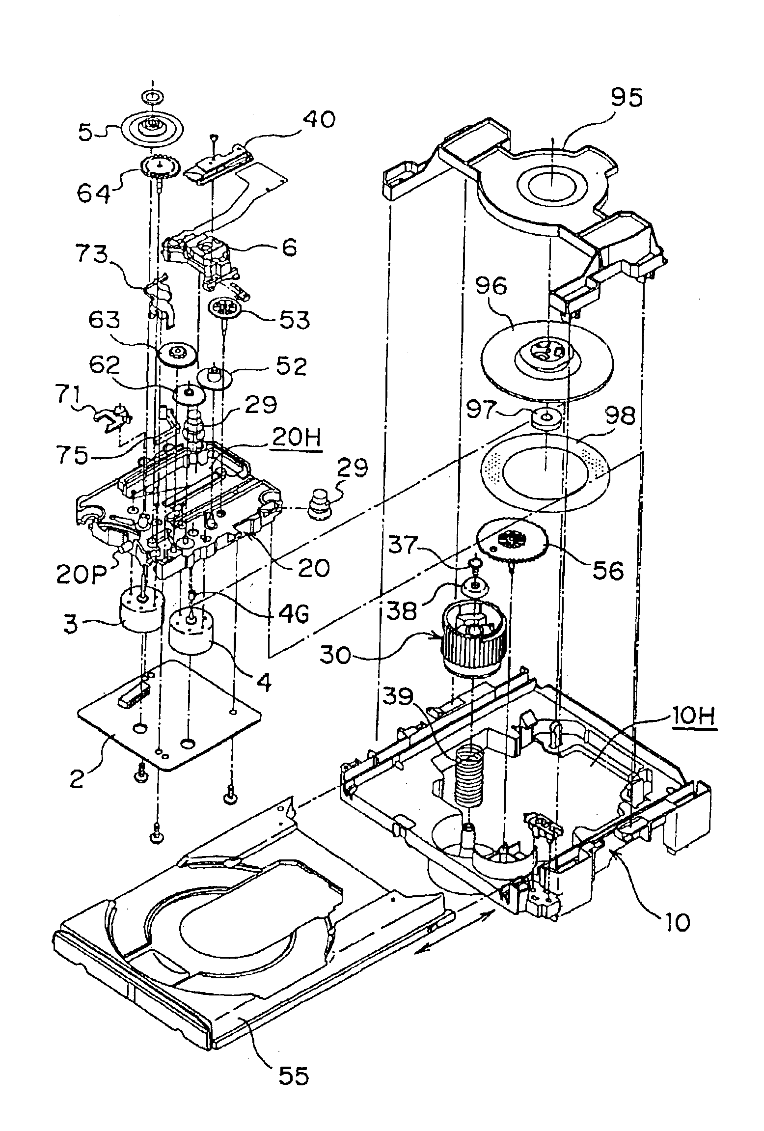
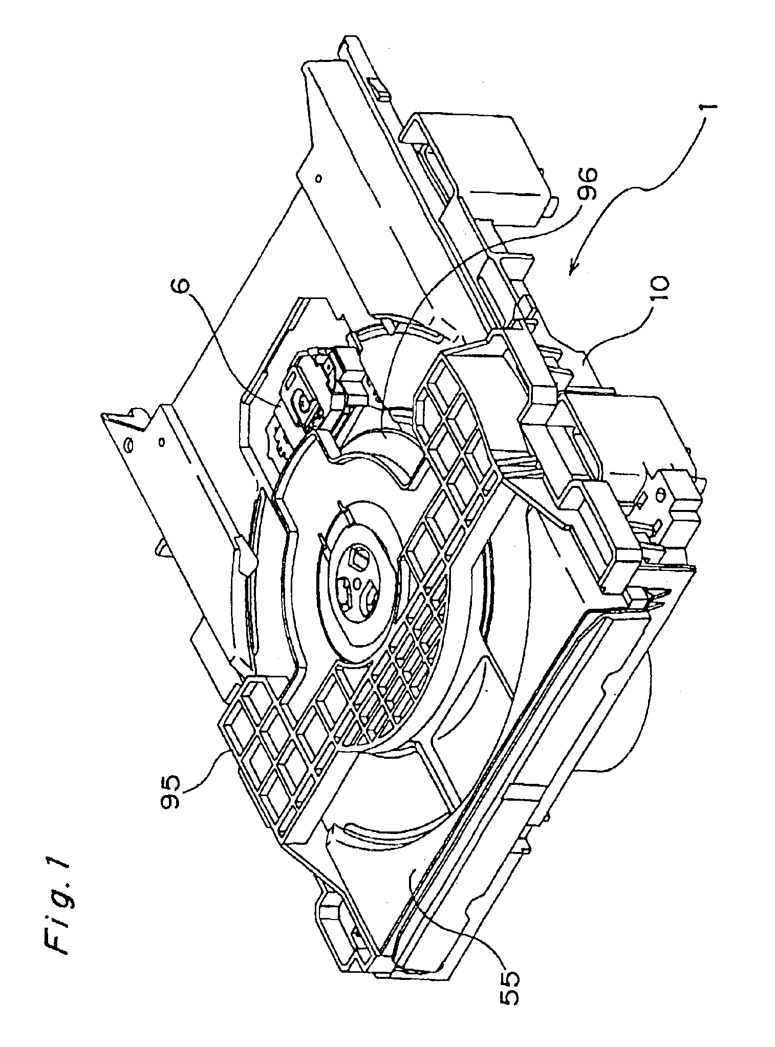
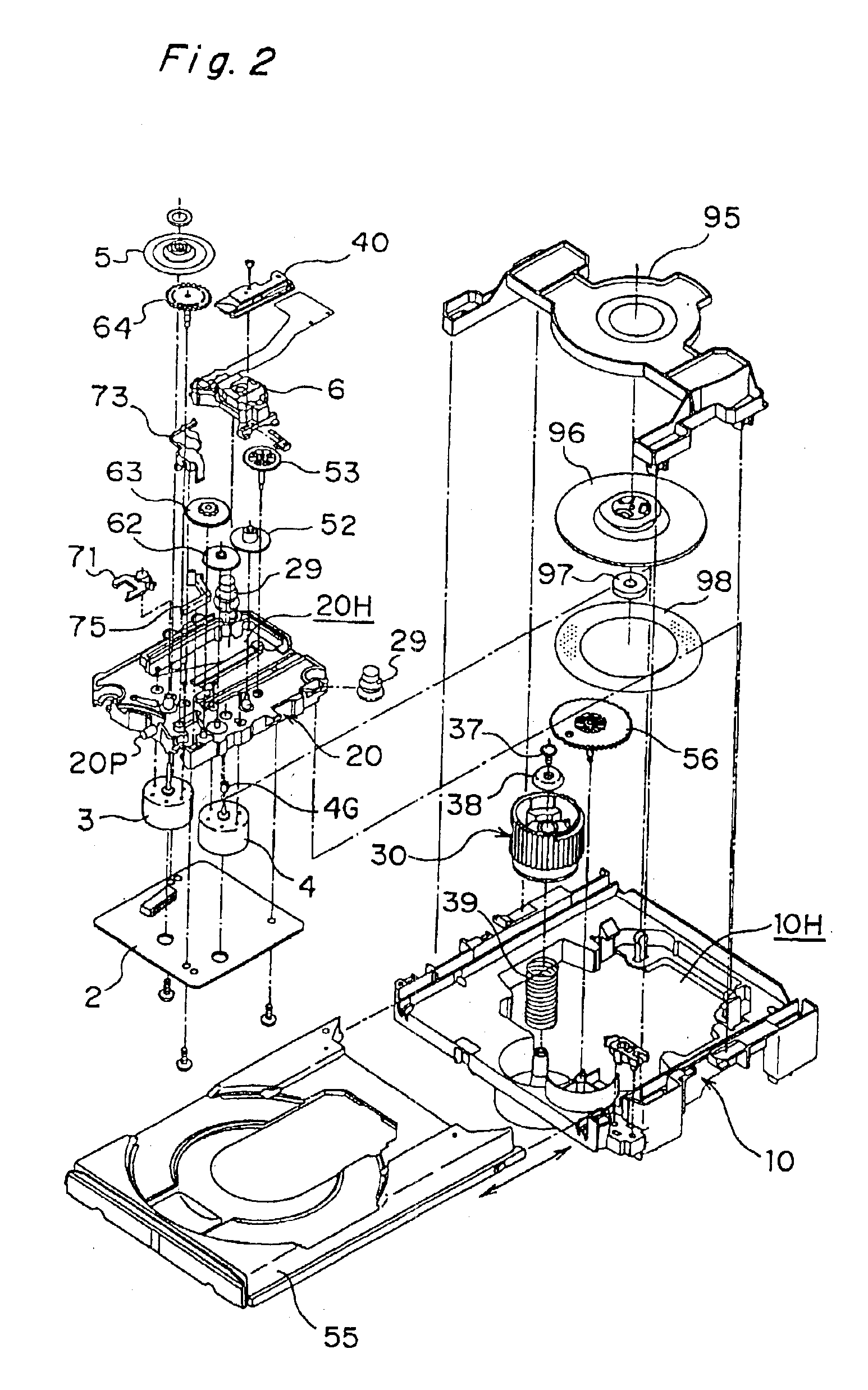
[0067]The preferred embodiments of the present invention are described below with reference to the accompanying figures. FIG. 1 is an overall perspective view of the assembled optical disk drive according to a preferred embodiment of the present invention. FIG. 2 is an exploded view of the disk drive shown in FIG. 1, and FIGS. 3 and 4 are enlarged views of parts of FIG. 2.

[0068]It should be noted that the terms “optical disk drive”, “disk drive”, and simply “drive” are used synonymously throughout this specification.

[0069]As will be known from these figures, an optical disk drive 1 according to this preferred embodiment comprises a drive base 10 as the installation base for major components of the drive 1, and a traverse base 20 as the support base for supporting the major part of the disk drive's drive mechanism.

[0070]The overall shape of the drive base 10 is a substantially square frame when seen in plan view. The traverse base 20 is arranged in an internal space 10H in the drive ...


PUM


Abstract

An optical disk drive includes a turntable, a first motor for turntable drive, an optical pickup and a drive mechanism arranged on a drive base and a separate traverse base that floats on the drive base. A loading drive mechanism drives a disk loading mechanism. A second motor can be driven in forward and reverse directions to supply drive power to the loading drive mechanism and a pickup drive mechanism. A drive power transfer path switching mechanism is used to switch the path through which drive power from the second motor is transferred to supply power to the loading drive mechanism and pickup drive mechanism. By continuously driving the second motor in one direction, then moving the optical pickup, raising or lowering the turntable, and transporting a disk can be accomplished in this sequence substantially continuously. By reversing the direction of motor drive, these operations can be accomplished substantially continuously in reverse direction in reverse sequence.

Description

[0001]This application is a Divisional of application of Ser. No. 09 / 494,654 filed Jan. 31, 2000 now U.S Pat. No. 6,741,536, currently pending.BACKGROUND OF THE INVENTION[0002]The present invention relates to an optical disk drive, also referred to herein as simply a disk drive, for recording a data signal and / or reproducing a data signal recorded to an optical disk, also referred to herein as simply a disc, used as a data storage medium. A Compact Disc or CD is exemplary of such data storage media.[0003]A disk drive typical of those related to the present invention has an opening on the front panel through which a disk tray opens and closes. After the tray is opened and a disk is loaded onto the tray, the tray is automatically closed, that is, retracted into the disk drive to a turntable.[0004]When a disk is loaded into this type of disk drive it is held between the turntable and a clamp and driven at a specific rotational speed so that data signals recorded to the disk can be read...

Claims


Application Information

Patent Timeline
IPC IPC(8): G11B33/08G11B17/04G11B17/056G11B25/04
CPCG11B17/0288G11B33/08G11B17/0565
Inventor ARIYOSHI, YUJITANAKA, TORUWAKIKAWA, MASANAOISHIOKA, KIYOSHI
Owner PANASONIC CORP
Why Eureka
Try Eureka