Flow rate sensor

a flow rate sensor and flow rate technology, applied in the field of sensors, can solve the problems of debased accuracy of conventional flow rate sensors, leakage of electricity, and uneven operation of propellers, and achieve the effect of convenient maintenance and improved flow ra

Inactive Publication Date: 2005-05-03
CHANG CHIEN TANG +1
View PDF4 Cites 20 Cited by
  • Summary
  • Abstract
  • Description
  • Claims
  • Application Information

AI Technical Summary

Benefits of technology

[0010]The main objective of the present invention is to provide

Problems solved by technology

However, the dirt in the fluid may be adhered on the blades of the propeller (31) after being used for a period of time and the propeller would not be smoothly operated.
Consequently, the accuracy of the conventional flow rate sensor is debased.
However, the chip (406) ma

Method used


Image

  • Flow rate sensor
  • Flow rate sensor
  • Flow rate sensor

Examples


Embodiment Construction

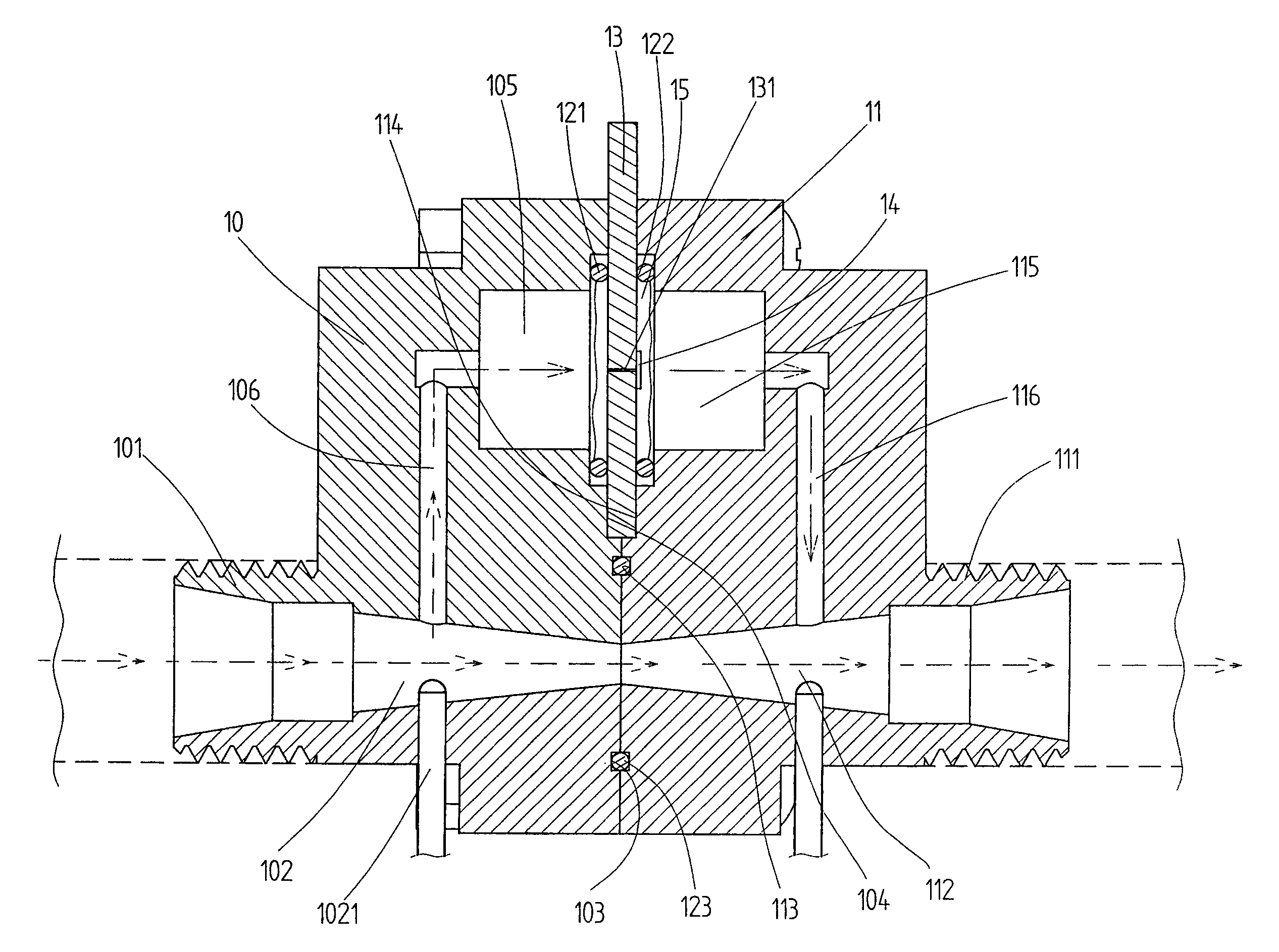
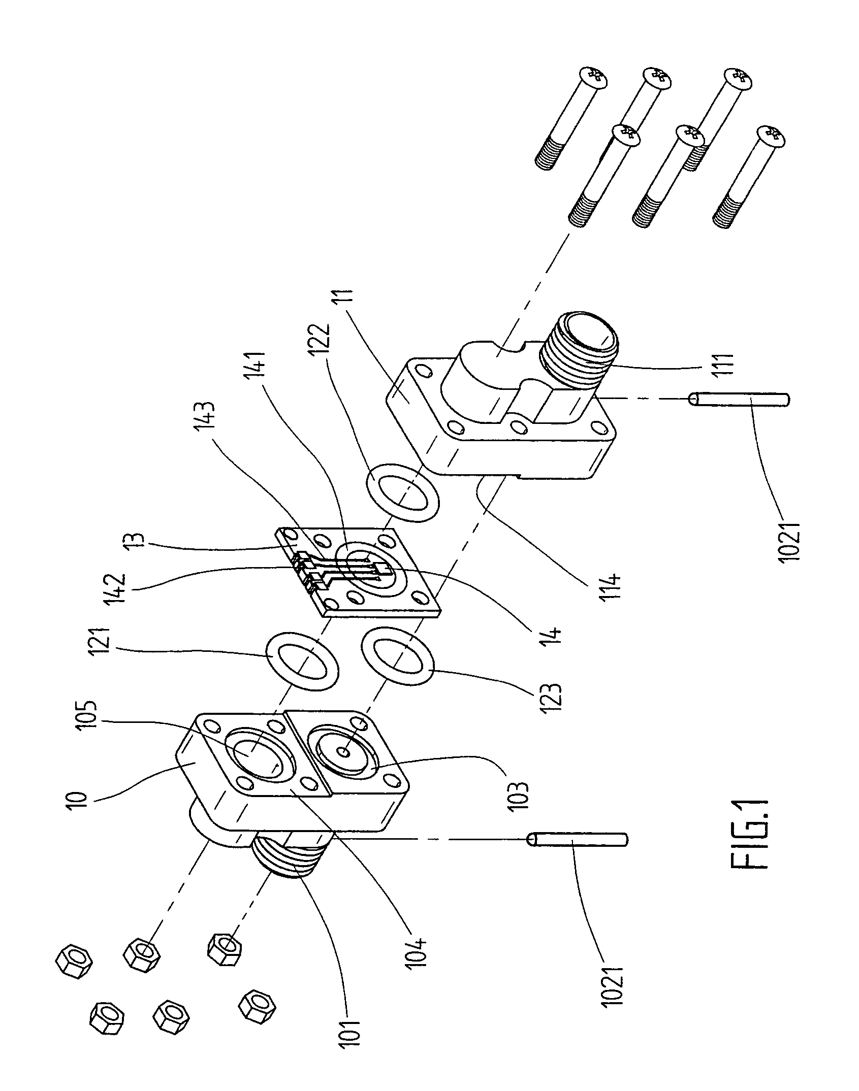
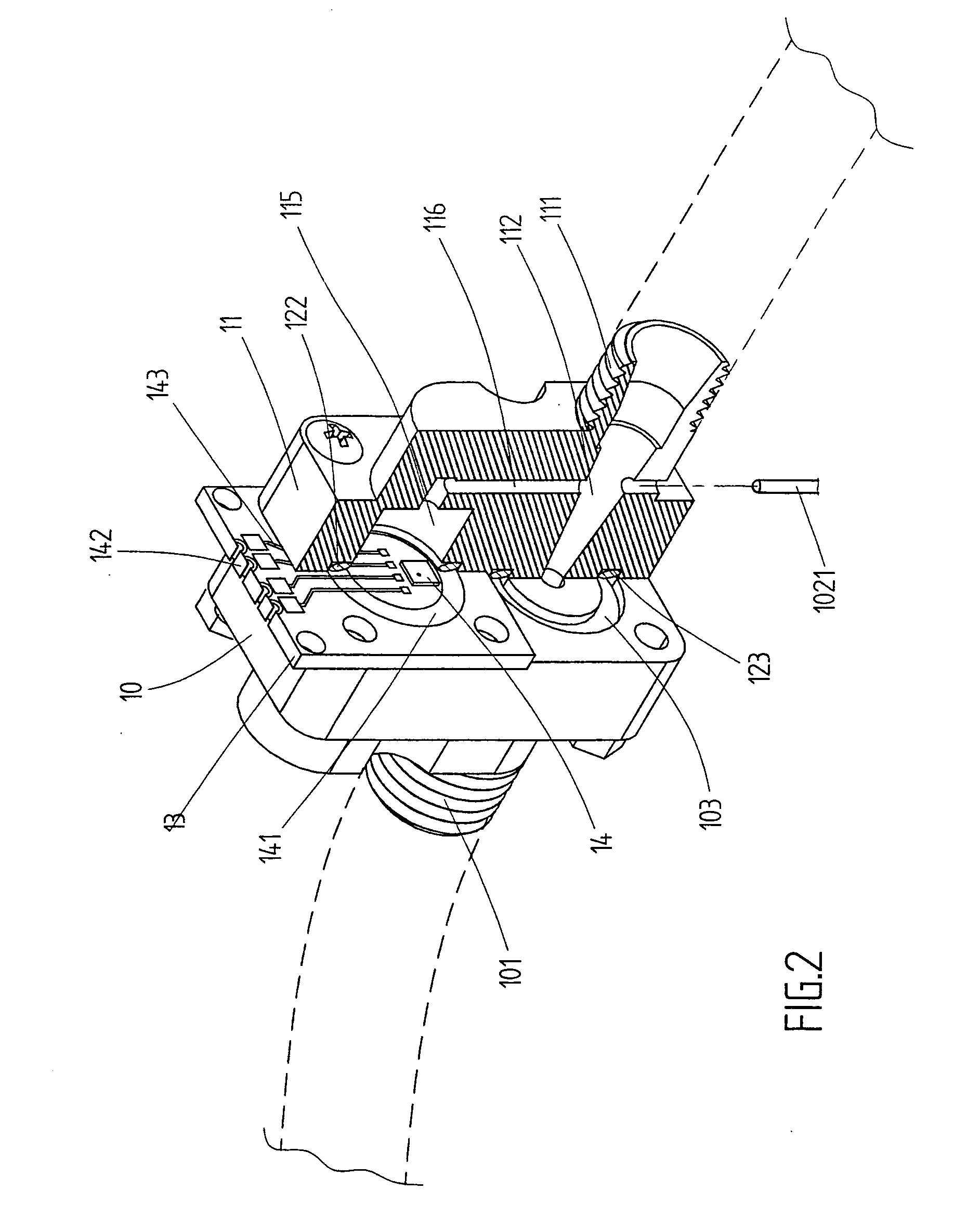
[0021]Referring to the drawings and initially to FIGS. 1–4, a flow rate sensor in accordance with the present invention comprises a first body (10), a second body (11) detachably airtightly abutting each other and a sensing device (13) sandwiched between the first body (10) and the second body (11).

[0022]The first body (10) has a first side opposite to the second body (11) and a second side facing the second body (11). A first joint (101) extends from the first side of the first body (10) and a first passage (102) defined in the first body (10). The first passage (102) extends through the first body (10) and the first joint (101), and has a diameter that is gradually reduced relative to the second body (11). A first annular (103) is defined in the second side of the first body (10) around the first passage (102). A first concave portion (104) is defined in a top portion of the second side of the first body (10) and a first cavity (105) is defined in a bottom of the concave portion ...


PUM


Abstract

A flow rate sensor includes a first body and a second body airtightly and detachably abutting each other. The first body and the second body respectively-include a passage defined therein. The two passages are tapered relative to each other. The first body and the second body respectively have a path defined therein. The two paths respectively communicate with a corresponding one of the two passages in the first and second bodies. A sensing device is airtightly sandwiched between the first and second body and corresponds to the two paths for calculating the different of the fluid that flows through the two passages in the first and second bodies.

Description

BACKGROUND OF THE INVENTION[0001]1. Field of the Invention[0002]The present invention relates to sensor, and more particularly to a flow rate sensor.[0003]2. Description of Related Art[0004]A conventional mechanical flow rate sensor in accordance with the prior art shown in FIG. 7 comprises tube (30) and a propeller (31) rotatably mounted in the tube (30). The propeller (31) peripherally abuts an inner periphery of the tube (30) such that the propeller (31) is rotated when the fluid passing through the propeller (31) in the tube (30).[0005]A magnetic sensor (301) is secured on an outer periphery of the tube (30). The propeller (31) includes multiple blades (not numbered) and a magnet (310) is securely in a distal end of a corresponding one of the multiple blades of the propeller (31). The magnetic sensor (301) measures the rotation rate of the propeller (31) by sensing the rotation force of the magnet (310) during turning around to calculate the flow rate in the tube (30).[0006]Howe...

Claims


Application Information

Patent Timeline
IPC IPC(8): G01F1/34G01F1/44
CPCG01F1/44
Inventor CHANG, CHIEN-TANGLIN, TAI-SHENG
Owner CHANG CHIEN TANG
Why Eureka
Try Eureka