Display apparatus having a structure for wall mounting

a technology of display apparatus and structure, which is applied in the field of display apparatus, can solve the problems of cumbersome user adjustment of object tilt, inability to minutely adjust object tilt, and complicated structure of conventional mounting rack, and achieve the effect of simple and minutely adjusted tilt structur

Inactive Publication Date: 2005-05-03
SAMSUNG ELECTRONICS CO LTD
View PDF20 Cites 94 Cited by
  • Summary
  • Abstract
  • Description
  • Claims
  • Application Information

AI Technical Summary

Benefits of technology

[0013]Accordingly, it is an object of the present invention to provide a display apparatus which has a simple tilting structure, and whose tilt is easily and minutely adjusted.
[0015]The foregoing and other objects of the present invention are achieved by providing a display apparatus comprising a display main body formed with a display part, further comprising: a lower hinge part provided in a rear lower part of the display main body to tilt the display main body against an installation plane; and a link assembly provided in a rear upper part of the display main body, and connecting the display main body to the installation plane, the link assembly including: a first link having a first end rotatably connected to the installation plane and an opposite second end; a second link having a first end rotatably connected to the display main body and a second end rotatably connected to the second end of the first link; and a spring member provided in at least one of the hinge parts of the first and second links and having the elasticity to restore the display main body toward the installation plane.

Problems solved by technology

However, the conventional mounting rack is not only complicated in structure because of the shock absorber having the gas damper and the wire, a locking member, etc., but also difficult and cumbersome for a user to adjust the tilt of the object because the object should be tilted after the locking member is released.
Further, because the object is stepwise tilted by the locking member, it is impossible to minutely adjust the tilt of the object.

Method used


Image

  • Display apparatus having a structure for wall mounting
  • Display apparatus having a structure for wall mounting
  • Display apparatus having a structure for wall mounting

Examples


Embodiment Construction

[0033]Reference will now be made in detail to the embodiments of the present invention, examples of which are illustrated in the accompanying drawings, wherein like reference numerals refer to like elements throughout. The embodiments are described below in order to explain the present invention by referring to the figures.

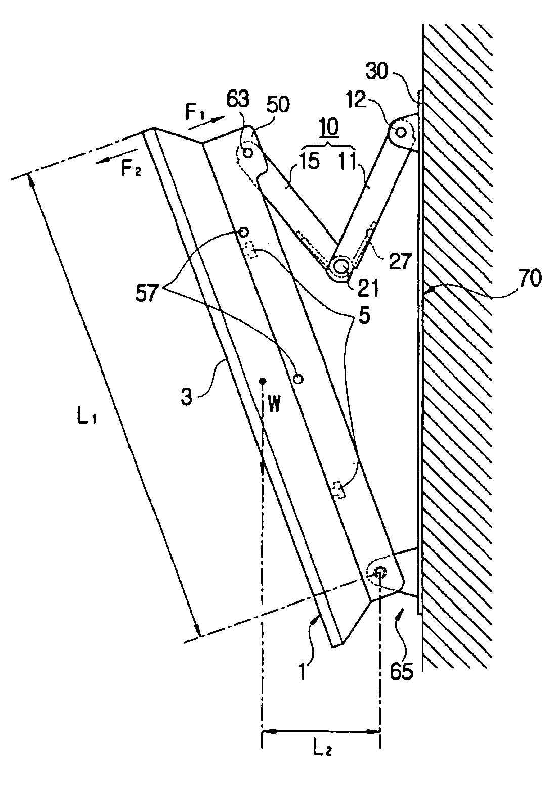
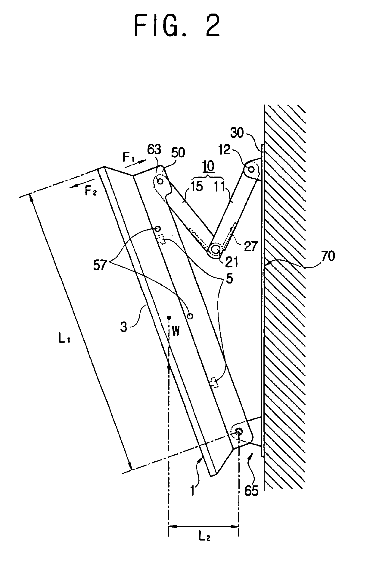
[0034]As illustrated in FIGS. 2 through 4, a display apparatus according to the present invention comprises a display main body 1 having a display part 3, and a mounting rack mounting the display main body 1 onto a predetermined installation plane and allowing the display main body 1 to be tilted. The mounting rack includes a main body bracket 50 supporting the display main body 1, a base bracket 30 rotatably supporting the main body bracket 50 and mounted onto a wall 70, and a link assembly 10 provided between the main body bracket 50 and the base bracket 30.

[0035]As illustrated in FIG. 3, two mounting racks are mounted onto the wall 70 in parallel, and one displ...


PUM


Abstract

A display apparatus having a display main body formed with a display part, further having a lower hinge part provided in a rear lower part of the display main body so as to tilt the display main body against an installation plane and a link assembly provided in a rear upper part of the display main body, and connecting the display main body to the installation plane. The link assembly includes a first link having a first end rotatably connected to the installation plane and an opposite second end and a second link having a first end rotatably connected to the display main body and a second end rotatably connected to the second end of the first link. The link assembly further includes a spring member provided in at least one of the hinge parts of the first and second links and has the elasticity to restore the display main body toward the installation plane.

Description

CROSS-REFERENCE TO RELATED APPLICATIONS[0001]This application claims the benefit of Korean Application No. 2002-29541, filed May 28, 2002, in the Korean Industrial Property Office, the disclosure of which is incorporated herein by reference.BACKGROUND OF THE INVENTION[0002]1. Field of the Invention[0003]The present invention relates to a display apparatus, and more particularly, to a display apparatus improved in structure for wall mounting.[0004]2. Description of the Related Art[0005]Generally, a display apparatus comprises a display main body having a display part, and a mounting rack to mount the display main body onto a predetermined installation plane.[0006]Recently, because the display part of the display main body is made of an LCD, a PDP, etc., the displaying area thereof becomes relatively enlarged and the thickness thereof becomes relatively thin, so that the display apparatus can be easily mounted onto a wall.[0007]Accordingly, there has been proposed a mounting rack to m...

Claims


Application Information

Patent Timeline
Patent Type & Authority Patents(United States)
IPC IPC(8): F16M13/02F16M11/02F16M11/10H04N5/64G06F1/16
CPCF16M11/10F16M13/02Y10S248/923F16M2200/041G06F1/16
Inventor HONG, YOU-SIKKIM, YOUNG-TAEBYOUN, DAE-HYOUN
Owner SAMSUNG ELECTRONICS CO LTD
Why Eureka
Try Eureka