Slide rail with two compression regions

Inactive Publication Date: 2005-05-10
JOH WINKLHOFER & SOHNE
View PDF7 Cites 8 Cited by
  • Summary
  • Abstract
  • Description
  • Claims
  • Application Information

AI Technical Summary

Benefits of technology

[0004]It is therefore the object of the present invention to provide a tensioning rail of the type mentioned at the start, which promises a cost benefit, especially when used in series production.

Problems solved by technology

Such a tensioning rail leads to a reduced number of different components and, consequently, to lower storage expenses, etc.

Method used


Image

  • Slide rail with two compression regions
  • Slide rail with two compression regions
  • Slide rail with two compression regions

Examples


Embodiment Construction

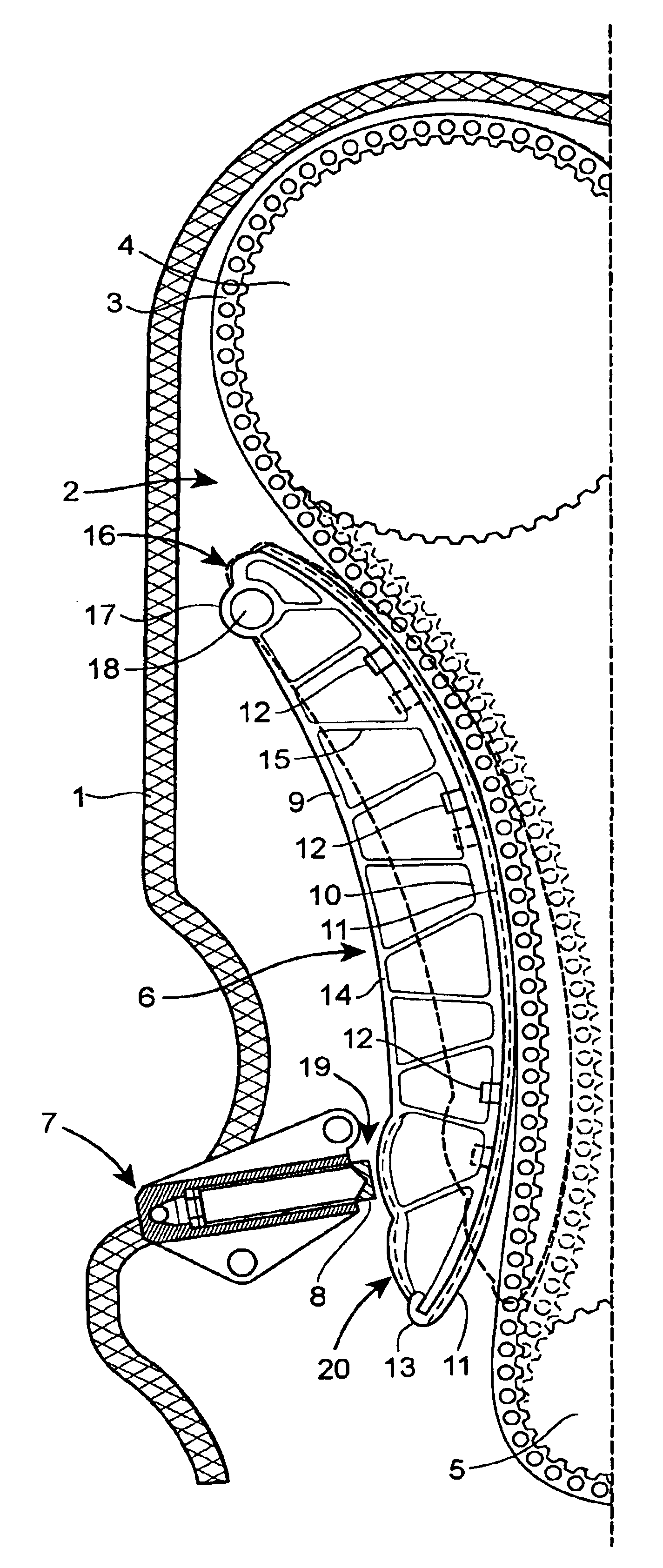
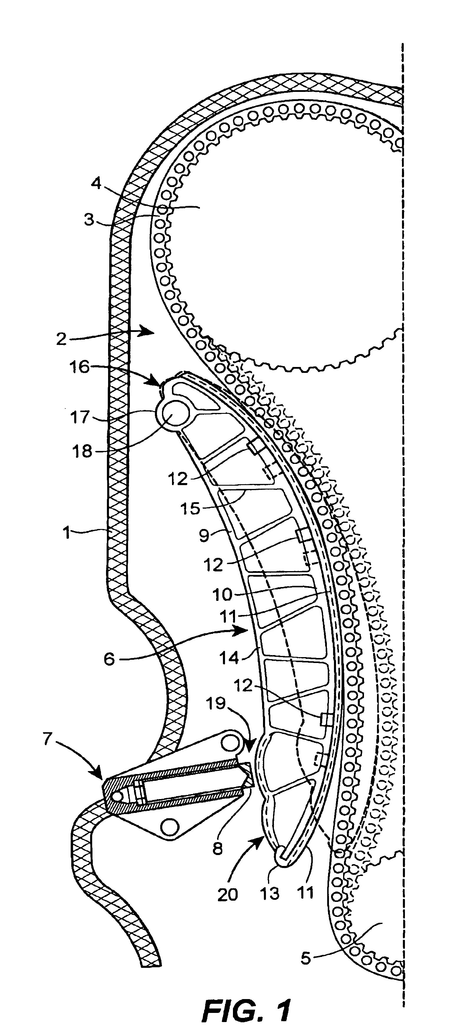
[0024]FIG. 1 shows schematically part of the chain drive housing 1 of a timing chain drive of a four-cylinder in-line engine. The timing chain 3 is guided around the upper camshaft gear 4 and the lower camshaft gear 5. These two camshaft gears 4 and 5 have provided between them a pivotably arranged tensioning rail 6 which is pressed against the outer side of the chain through a chain tensioner 7. The chain tensioner 7 is a chain tensioner 7 which is secured to the engine and provided with a linearly displaceable tensioning piston 8, said tensioning piston being adapted to have applied thereto a tensioning force by a helical spring, which is not shown in detail, as well as via a pressure chamber (not shown in detail either) communicating with the engine oil hydraulic system. In general, any suitable embodiment of chain tensioners, which applies a force to the tensioning rail 6 in a suitable manner, can be used.

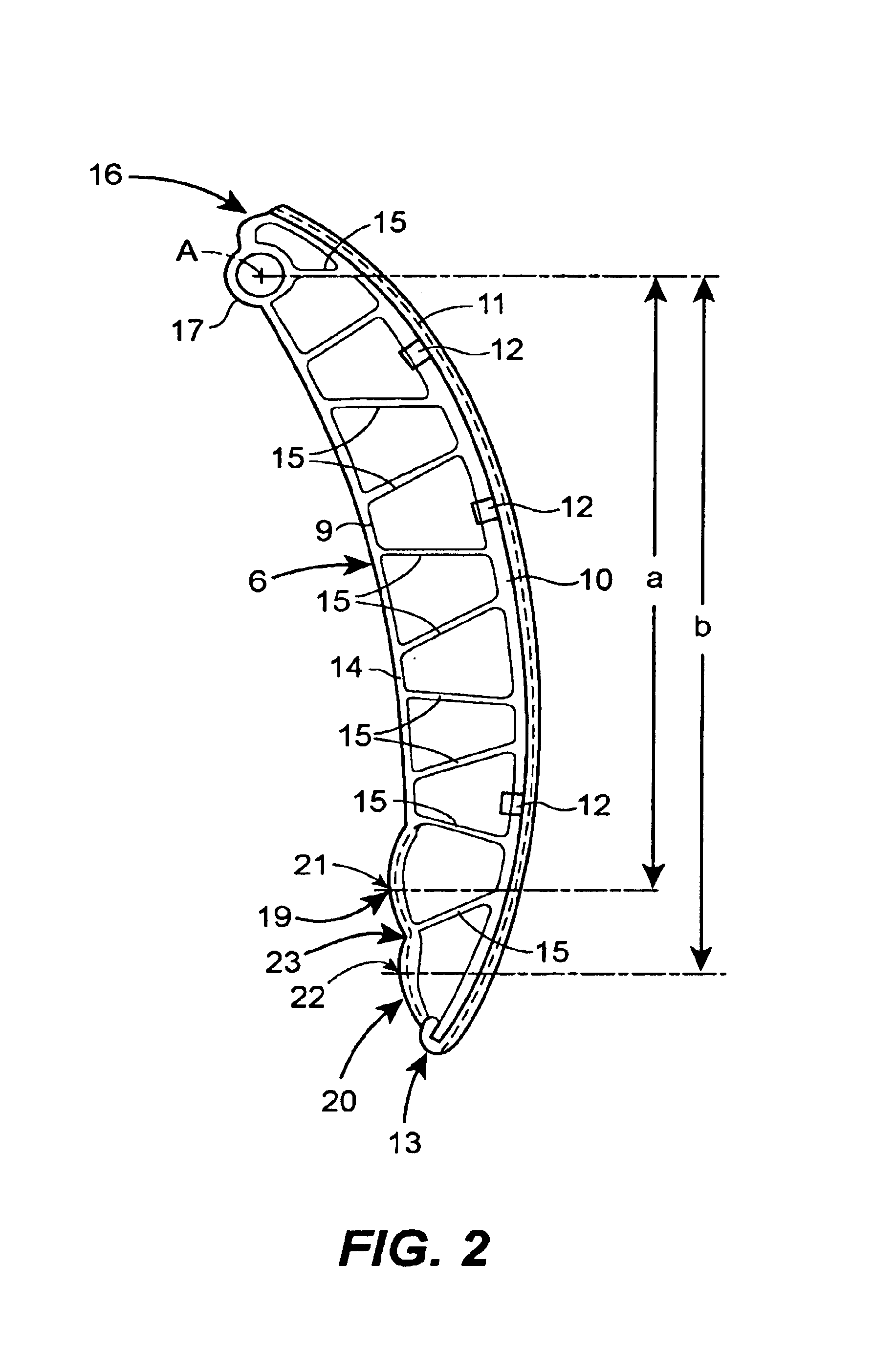
[0025]The tensioning rail 6 comprises a carrier body 9, which has a truss-...


PUM


Abstract

The present invention relates to a tensioning rail for a traction drive, especially for an internal combustion engine, said tensioning rail comprising a fastening end section with a pivotable fastening means and a tensioning arm area having, at a predetermined distance from said pivotable fastening means, a pressure-application region for contact with a tensioning piston of a tensioning device, at least one second pressure-application region being arranged on the tensioning arm area at a predetermined different distance from said pivotable fastening means.

Description

REFERENCE TO RELATED APPLICATIONS[0001]This disclosure claims the benefit of the filing date of International Application No. PCT / EP02 / 06602, having an international filing date of Jun. 14, 2002, which designated the United States of America, and this disclosure is the United States national stage of that international application. This disclosure further claims priority to Germany patent application DE 201 15 742.2, filed Sep. 19, 2001.FIELD OF THE INVENTION[0002]The present invention relates to a tensioning rail for a traction device, especially for an internal combustion engine, comprising a fastening end section with a pivotable fastening means and a tensioning arm area having, at a predetermined distance from said pivotable fastening means, a pressure-application region for contact with a tensioning piston of a tensioning device.BACKGROUND OF THE INVENTION[0003]Such tensioning rail arrangements with chain tensioners acting thereon are known especially for timing chain drives in...

Claims


Application Information

Patent Timeline
IPC IPC(8): F16H7/08F16H7/00F16H7/12
CPCF16H7/08F16H2007/0872
Inventor FINK, THOMASZIMMERMANN, STEFANBACHMAIR, PETER
Owner JOH WINKLHOFER & SOHNE
Why Eureka
Try Eureka