Locking mechanism for connector

a technology of locking mechanism and connector, which is applied in the direction of coupling device connection, coupling parts engagement/disengagement, electrical apparatus, etc., can solve the problems of poor connection and impaired reliability of electric connection, and achieve high fitting reliability and solve the effect of backlash

Inactive Publication Date: 2005-05-10
YAZAKI CORP
View PDF5 Cites 17 Cited by
  • Summary
  • Abstract
  • Description
  • Claims
  • Application Information

AI Technical Summary

Benefits of technology

[0018]In view of the above circumstance, an object of this this invention is to dissolve the backlash between a female connector and a male connector to provide a connector locking mechanism with high fitting reliability.

Problems solved by technology

However, the connector described above presents the following problem to be solved.
Particularly, in a waterproof connector, a water drop or dust will invade from the gap so that poor connection occurs.
The reliability of the electric connection will be impaired.

Method used


Image

  • Locking mechanism for connector
  • Locking mechanism for connector
  • Locking mechanism for connector

Examples


Embodiment Construction

[0038]Now referring to the drawings, an explanation will be given of an embodiment of this invention.

[0039]FIGS. 1 to 5 show an embodiment of the connector locking mechanism according to this invention.

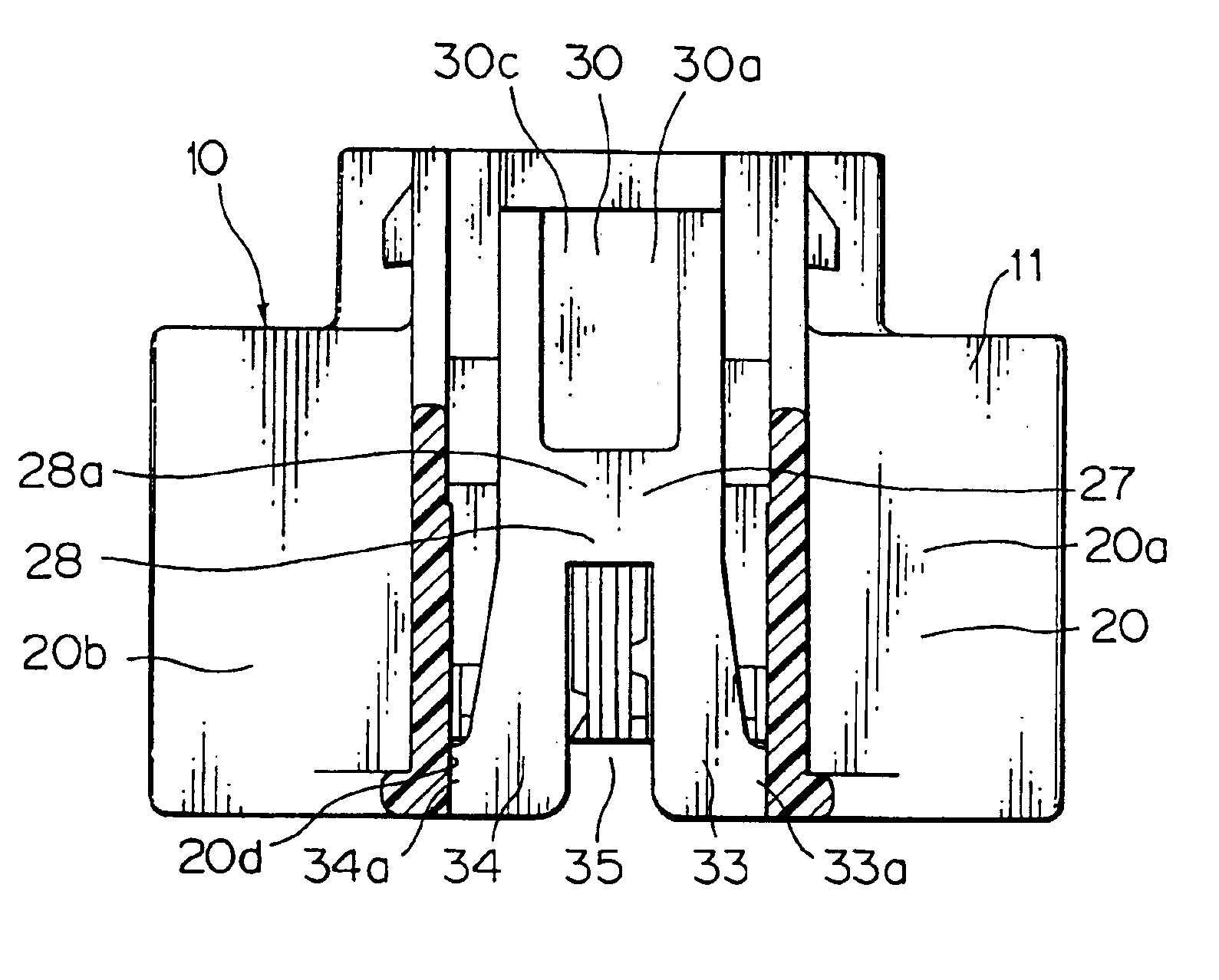
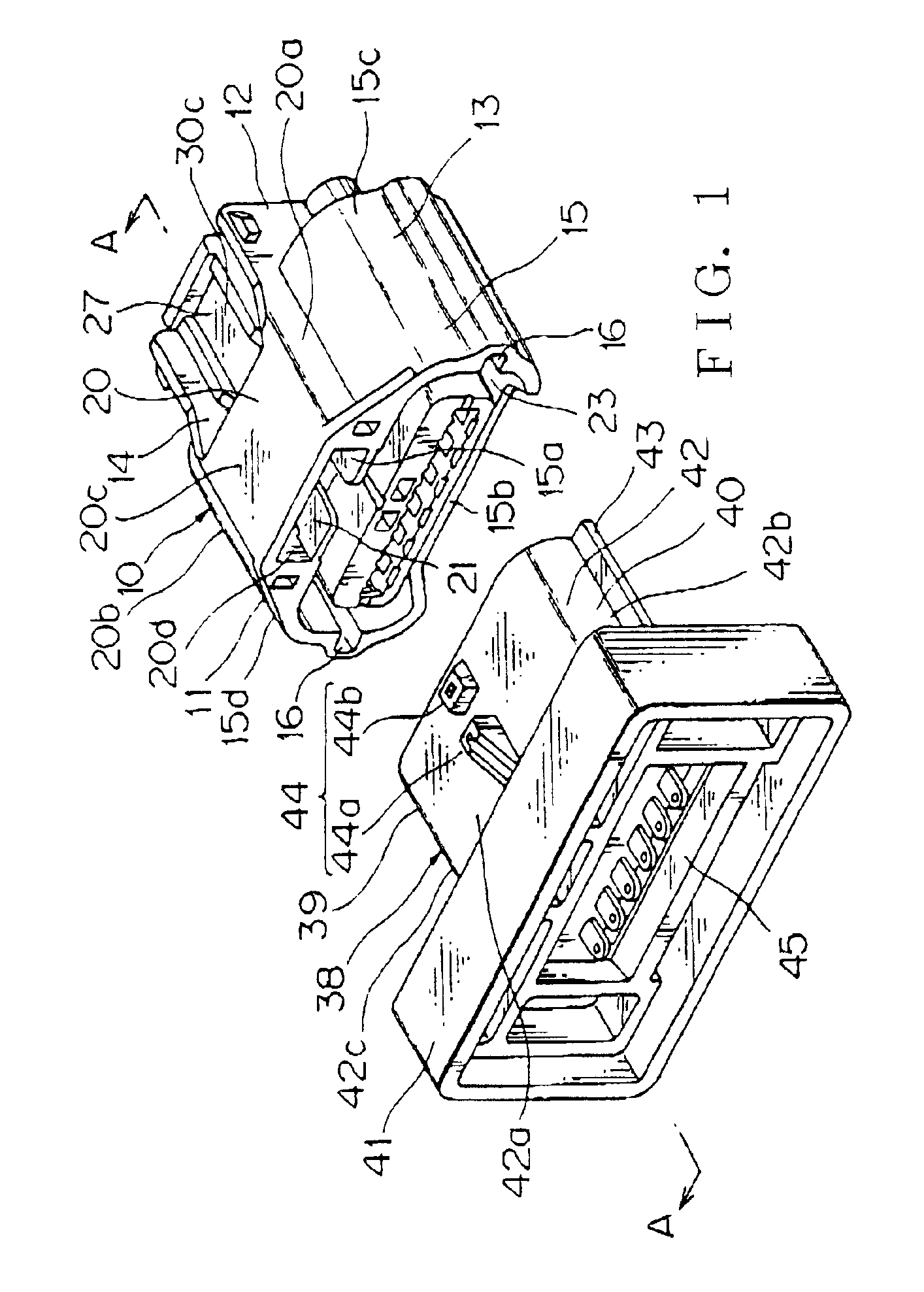
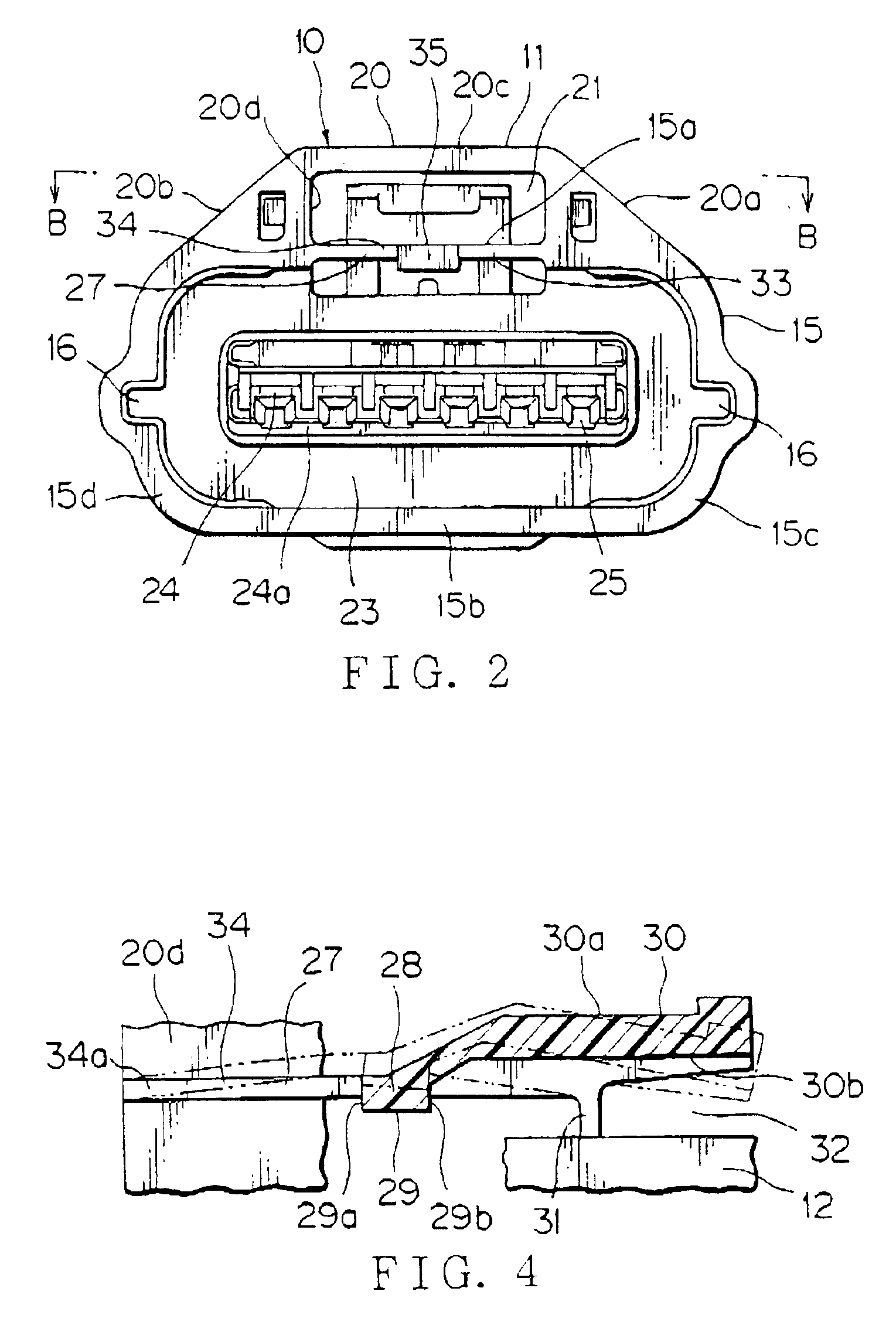
[0040]As seen from FIG. 1, a male connector 10 and a female connector (complementary connector) 38 constitute a pair of connectors. The female connector 38 includes a female connector housing 39 and a male terminal (not shown) equipped with an electric wire (not shown). The male connector 10 includes a male connector housing 11 and a female terminal (not shown) equipped with an electric wire.

[0041]The male connector housing 11 includes an external hood 15, a housing main body 12 inside the hood 15, a terminal chamber 24 which accommodates female terminals and a locking arm 27 which faces the ring-shaped space 23.

[0042]The hood 15 constitutes an outer wall of the ring-shaped space 23, and is composed of upper and lower walls 15a and 15b and side walls 15c and 15d which couple the upper...


PUM


Abstract

A locking arm 27 is supported by a fulcrum 31 attached to a body 28 and a pair of coupling portions 33, 34. When an operation portion 30 is pressed down, an engaging portion 29 located between the fulcrum 31 and the coupling portions 33, 34 is shifted vertically to a direction of coupling a connector 10 with a complementary connector 38. The coupling portions 33, 34 are made in parallel to the direction of coupling the connector 10 with the complementary connector 38. The pair of coupling portions 33 and 34 are formed as a pair of legs. A sliding groove 35 is formed between the pair of legs 33 and 34 so as to correspond to an engaging portion 44 of the complementary connector 38. The engaging portion 44 will be slid into the sliding groove 35. In such a configuration, the locking mechanism can remove backlash between a female connector and a male connector to provide high coupling accuracy.

Description

BACKGROUND OF THE INVENTION[0001]1. Field of the Invention[0002]This invention relates to a locking mechanism for a connector which is used for connection of a wire harness for a vehicle and has a locking arm to be engaged with an engaging portion of a complementary connector.[0003]2. Description of the Related Art[0004]FIGS. 6 and 7 show an example of a technique related to such a kind of locking mechanism, which has been proposed by the applicant of this application and is disclosed in JP-A-6-89756.[0005]As shown in FIG. 6, a male connector 50 which it to incorporate a female terminal 68 has a hood 53 at its front half 51 in the longitudinal direction. An arch-shaped swelling wall 54 is formed outside and integrally to the hood 53. A ring-shaped space 55 corresponding to a complementary female connector 65 is formed inside the hood 53.[0006]Inside the swelling wall 54, a locking arm 56 to be engaged with the engaging portion 67 of the female connector 65 is formed. The locking arm...

Claims


Application Information

Patent Timeline
Patent Type & Authority Patents(United States)
IPC IPC(8): H01R13/627H01R13/629H01R13/639H01R13/62
CPCH01R13/6272H01R13/629H01R13/62
Inventor YAMAWAKI, TAKANORI
Owner YAZAKI CORP
Why Eureka
Try Eureka