Water flow sensor and water heater

A technology of water flow sensor and water flow channel, which is applied in the direction of fluid heater, lighting and heating equipment, lifting valve, etc., and can solve the problems of complex connection structure and large space occupation

Pending Publication Date: 2021-06-01
WUHU MIDEA KITCHEN & BATH APPLIANCES MFG CO LTD +1
View PDF6 Cites 0 Cited by
  • Summary
  • Abstract
  • Description
  • Claims
  • Application Information

AI Technical Summary

Problems solved by technology

Since the water flow sensor and the water regulating valve are connected in series to the pipeline of the water heater, it takes up a lot of space and the connection structure is relatively complicated

Method used


Image

  • Water flow sensor and water heater
  • Water flow sensor and water heater
  • Water flow sensor and water heater

Examples


Embodiment 1

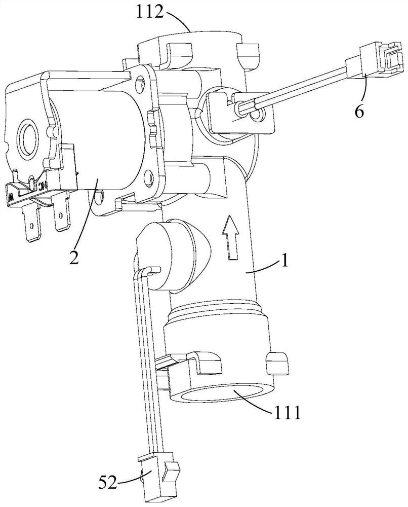
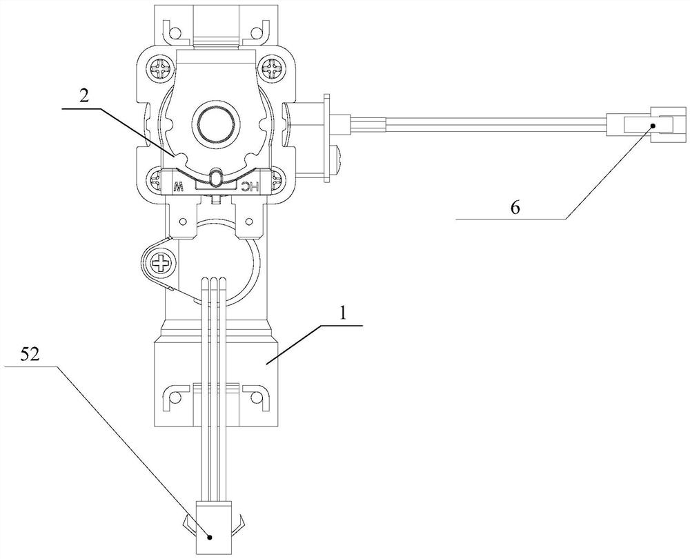
[0081] A water flow sensor, comprising: a water valve body 1 and a valve assembly, such as figure 1 and image 3 shown.

[0082] Specifically, the water valve body 1 is provided with a water flow channel 11, such as Figure 4 and Figure 6 shown. The water flow channel 11 has a water inlet 111 and a water outlet 112, such as figure 1 , Figure 4 and Figure 6 shown. The water valve body 1 is also provided with a valve port 113 communicated with the water flow passage 11, such as Figure 6 As shown, the valve port 113 is located between the water inlet 111 and the water outlet 112 .

[0083] The valve assembly is located at the valve port 113 and is connected to the water valve body 1 for opening or closing the valve port 113, such as Figure 4 and Figure 6 As shown, and in the case of opening the valve port 113, the water passage 12 is defined between the water valve body 1, as Figure 6 As shown, and the two ends of the water passage 12 communicate with the water ...

Embodiment 2

[0094] On the basis of Embodiment 1, further, a water chamber 23 is formed between the valve 21 and the sealing member 22, such as Figure 5 shown. Water valve body 1 is provided with water port 114, and water port 114 is positioned at the upstream side of valve port 113, as Figure 5 shown. The sealing member 22 is provided with a water hole 224 corresponding to the water port 114, such as Figure 5 As shown, to communicate with the water chamber 23 and the water inlet 111.

[0095] A water chamber 23 is formed between the valve 21 and the sealing member 22, and the water chamber 23 is connected to the water inlet 111 of the water valve body 1 through the water hole 224 on the sealing member 22 and the water outlet 114 on the water valve body 1 and the valve port 113 is located on the downstream side of the water port 114 and thus communicates with the water outlet 112, then when the valve assembly closes the valve port 113, the side of the sealing member 22 away from the ...

Embodiment 3

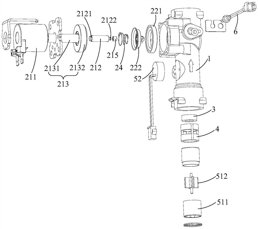
[0106] On the basis of the second embodiment, further, the sealing member 22 includes: a sealing gasket 221 and a supporting member 222 .

[0107] Specifically, the sealing gasket 221 is in contact with the valve port 113, and is suitable for defining the water passage 12 with the water valve body 1, such as Figure 6 shown. The support member 222 is connected with the gasket 221 and is located between the valve 21 and the gasket 221, such as figure 2 and Figure 5 As shown, it is used to support the gasket 221 and cooperate with the valve 21.

[0108] The sealing member 22 includes a sealing gasket 221 and a support member 222, the sealing gasket 221 can be closely attached to the water valve body 1 to play a sealing role; the supporting member 222 is connected to the sealing gasket 221 and is located between the valve 21 and the sealing member 22, When subjected to the force of the valve 21 , it can strongly support the sealing gasket 221 to prevent the sealing gasket 221 ...


PUM


Abstract

The invention provides a water flow sensor and a water heater. The water flow sensor comprises a water valve body, wherein the water valve body is provided with a water flow channel, the water flow channel is provided with a water inlet and a water outlet, the water valve body is further provided with a valve port communicating with the water flow channel, and the valve port is located between the water inlet and the water outlet; and a valve assembly, wherein the valve assembly is arranged at the valve port, connected with the water valve body and used for opening or closing the valve port, a water passing channel is defined between the valve assembly and the water valve body under the condition that the valve port is opened, and the two ends of the water passing channel communicate with the water inlet and the water outlet correspondingly. A stop valve is integrated on the basis of the water flow sensor, so that the water flow sensor has the functions of sensing the water flow and adjusting the water flow, a water adjusting valve in the prior art can be omitted, the space occupied by a water adjusting valve near a pipeline of the water heater is saved, a connecting structure of the water adjusting valve and the pipeline is omitted, accordingly, the space is saved, the product structure is simplified, and the production cost is reduced.

Description

technical field [0001] The invention relates to the technical field of water heaters, in particular to a water flow sensor and a water heater including the water flow sensor. Background technique [0002] Water heaters in the related art are generally respectively equipped with a water flow sensor and a water regulating valve, the water flow sensor is used to detect the water flow, and the water regulating valve is used to adjust the water volume. Since the water flow sensor and the water regulating valve are connected in series to the pipeline of the water heater, the occupied space is relatively large, and the connection structure is relatively complicated. Contents of the invention [0003] In order to solve at least one of the above technical problems, an object of the present invention is to provide a water flow sensor. [0004] Another object of the present invention is to provide a water heater comprising the above-mentioned water flow sensor. [0005] In order to...

Claims


Application Information

Patent Timeline
IPC IPC(8): F24H9/20F16K31/06F16K1/32
CPCF16K31/0675F16K31/0655F16K1/32F24H15/238F24H15/305
Inventor 易青伟梁泽锋梁国荣
Owner WUHU MIDEA KITCHEN & BATH APPLIANCES MFG CO LTD
Why Eureka
Try Eureka