Food processor

A technology for food cooking machines and machine bases, which can be used in home appliances, applications, kitchen utensils, etc. It can solve the problems of poor alignment of the motor shaft and the knife shaft, and high noise, so as to improve the user experience, reduce noise, and reduce noise. The effect of fit clearance

Active Publication Date: 2021-02-05
GUANGDONG MIDEA CONSUMER ELECTRICS MFG CO LTD
View PDF23 Cites 0 Cited by
  • Summary
  • Abstract
  • Description
  • Claims
  • Application Information

AI Technical Summary

Problems solved by technology

However, due to the gap between the upper connector and the lower connector, the alignment between the motor shaft and the cutter shaft is not good. During the rotation of the motor, the vibration and shaking of the cup body are more obvious and the noise is louder.

Method used


Image

  • Food processor
  • Food processor
  • Food processor

Examples


Embodiment 1

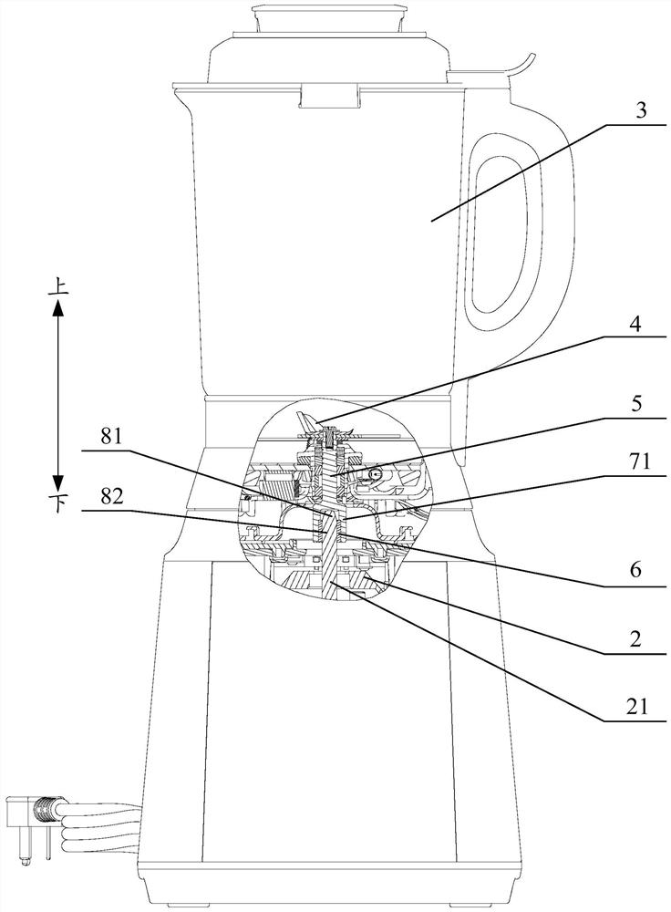
[0081] The clutch part is a one-way bearing 6.

[0082] The one-way bearing 6 (or needle roller clutch, overrunning clutch) is a kind of bearing that can rotate freely in one direction and is locked in the other direction. Therefore, the one-way bearing 6 is installed on the connecting shaft 7, and the The cooperating shaft 8 is inserted into the one-way bearing 6. When the one-way bearing 6 is locked, the cooperating shaft 8 can rotate synchronously with the connecting shaft 7 to realize the driving of the drive shaft 21 to the knife shaft 5. When the one-way bearing 6 can rotate freely At this time, the matching shaft 8 can be disengaged from the one-way bearing 6, and then the separation of the machine base 1 and the stirring cup 3 can be realized. Therefore, using the one-way bearing 6 as the clutch part can directly adopt standard parts for assembly, which is easy to obtain materials and has high stability, which is beneficial to market promotion of the product. In addit...

Embodiment 2

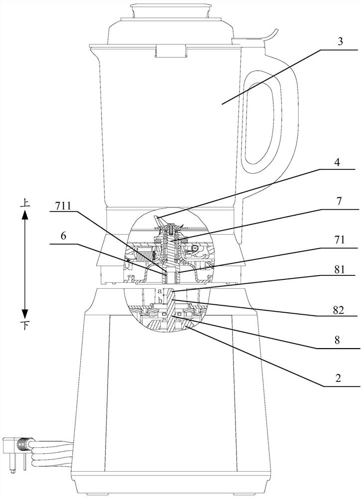
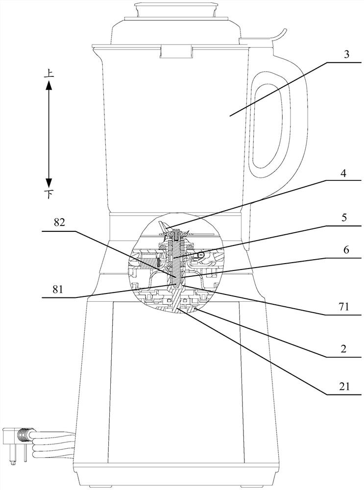
[0103] The difference from Embodiment 1 is that the drive shaft 21 is configured as the connecting shaft 7, and the cutter shaft 5 is configured as the mating shaft 8, such as image 3 and Figure 4 shown.

[0104] The principle is basically the same as that of Embodiment 1, and will not be repeated here.

Embodiment 3

[0106] The clutch part includes a fixed sleeve, which is fixedly connected with the connecting shaft 7, the cross section of the inner space of the fixed sleeve is non-circular, and the end of the mating shaft 8 close to the connecting shaft 7 is formed to match the shape of the fixed sleeve The connecting section is suitable for inserting or separating from the fixing sleeve.

[0107] The clutch part includes a fixed sleeve, which is fixedly connected with the connecting shaft 7, realizing the assembly and cooperation of the clutch part and the connecting shaft 7; the section of the fixed sleeve is non-circular (such as D-shaped, triangular, X-shaped, etc.), It can be inserted and matched with the non-circular connecting section on the matching shaft 8 to drive the matching shaft 8 to rotate synchronously. When the connecting section comes out of the fixed sleeve, the normal separation of the machine base 1 and the stirring cup 3 can be realized. The structure and principle ar...


PUM

PropertyMeasurementUnit
Lengthaaaaaaaaaa

Abstract

The invention provides a food processor which comprises a machine base, wherein a driving device is arranged in the machine base, and the driving device comprises a driving shaft; a stirring cup whichis placed on the machine base; a cutter set which comprises a cutter arranged in the stirring cup and a cutter shaft connected with the cutter, wherein one of the cutter shaft and the driving shaft is configured to be a connecting shaft, and the other one is configured to be a matching shaft; and a clutch part which is mounted on the connecting shaft and is suitable for being connected with the matching shaft to enable the driving shaft to drive the cutter shaft to rotate or be separated from the matching shaft to enable the stirring cup to be separated from the base. An upper connector and alower connector are replaced by the clutch part, so that the cutter shaft and the driving shaft are directly matched with the clutch part, the coaxiality of the cutter shaft and the driving shaft isimproved, the fit clearance between the cutter shaft and the driving shaft is reduced, shaking and vibration of the stirring cup are reduced, noise is reduced, and the use experience of a user is improved; and two parts, namely the upper connector and the lower connector, are replaced by one clutch part, so that the product structure is simplified, and the production cost is reduced.

Description

technical field [0001] The present invention relates to the technical field of food processing devices, in particular to a food cooking machine. Background technique [0002] At present, the stirring cups of food cooking machines such as wall breaking machines are generally detachably arranged on the machine base. The bottom of the stirring cup is provided with a lower connector, and the upper part of the machine base is provided with an upper connector. The connector is coupled with the lower connector, and when the motor in the machine base rotates, the cutter in the mixing cup is driven by the connector to rotate, stirring and pulverizing the food in the cup. However, due to the gap between the upper connector and the lower connector, the alignment between the motor shaft and the cutter shaft is not good. During the rotation of the motor, the vibration and shaking of the cup body are relatively obvious, and the noise is relatively large. Contents of the invention [00...

Claims


Application Information

Patent Timeline
IPC IPC(8): A47J43/046A47J43/08
CPCA47J43/046A47J43/085
Inventor 招绍坤刘云祥
Owner GUANGDONG MIDEA CONSUMER ELECTRICS MFG CO LTD
Why Eureka
Try Eureka