Elbow prosthesis

a technology for elbows and prostheses, applied in the field of elbow prostheses, can solve the problems of screw thread or tapping distortion, screw positioning skewed, and the inability to mount locking elements, and achieve the effect of adequate positioning of locking elements and efficient immobilization of locking elements

Active Publication Date: 2005-05-10
TORNIER SA SAINT ISMIER
View PDF7 Cites 131 Cited by
  • Summary
  • Abstract
  • Description
  • Claims
  • Application Information

AI Technical Summary

Benefits of technology

[0007]Thanks to the invention, the guiding means ensure an adequate positioning of the locking element with respect to the ulnar component before the blocking means are employed to effect an efficient immobilization of the locking element with respect to the ulnar component. In other words, the blocking means do not serve to bring the locking element in a configuration allowing its blocking, this function being performed by the guiding means which may be positioned and configured to ensure this function best.

Problems solved by technology

It has proved in practice that the positioning of the locking element on the ulnar component is not always optimum when such a screw is tightened, which may lead to a skewed positioning of the screw with respect to the tapping, to such a point that the thread of the screw or the tapping may be distorted, thus preventing the locking element from being mounted.
As a result, such an ulnar component must most often be fitted while the articulation of the elbow is in maximum flexion, which renders the surgeon's work more complex.
It even happens that such fitting in maximum flexion is not possible, particularly in the case of marked obesity of the patient.

Method used


Image

  • Elbow prosthesis
  • Elbow prosthesis
  • Elbow prosthesis

Examples


Embodiment Construction

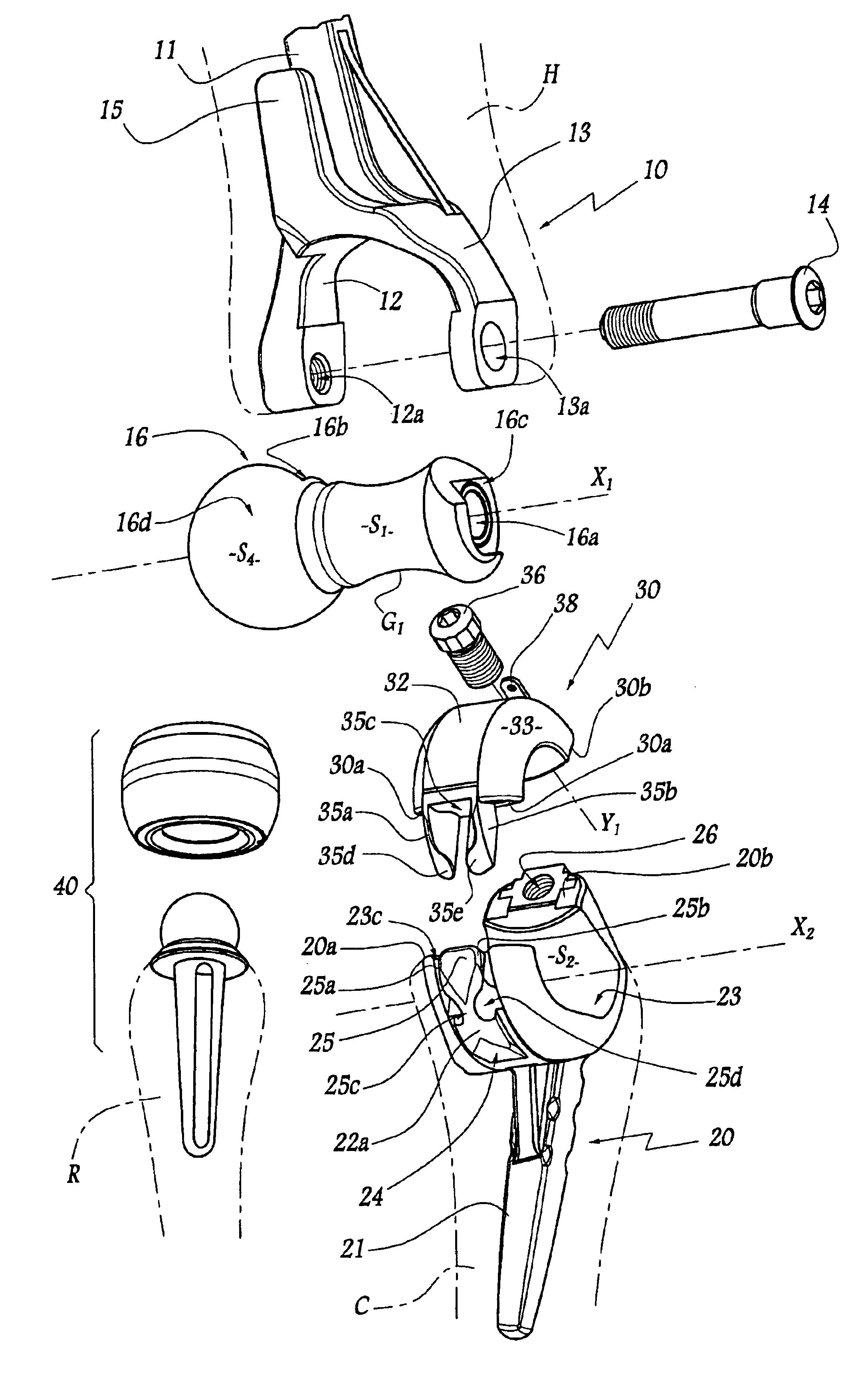
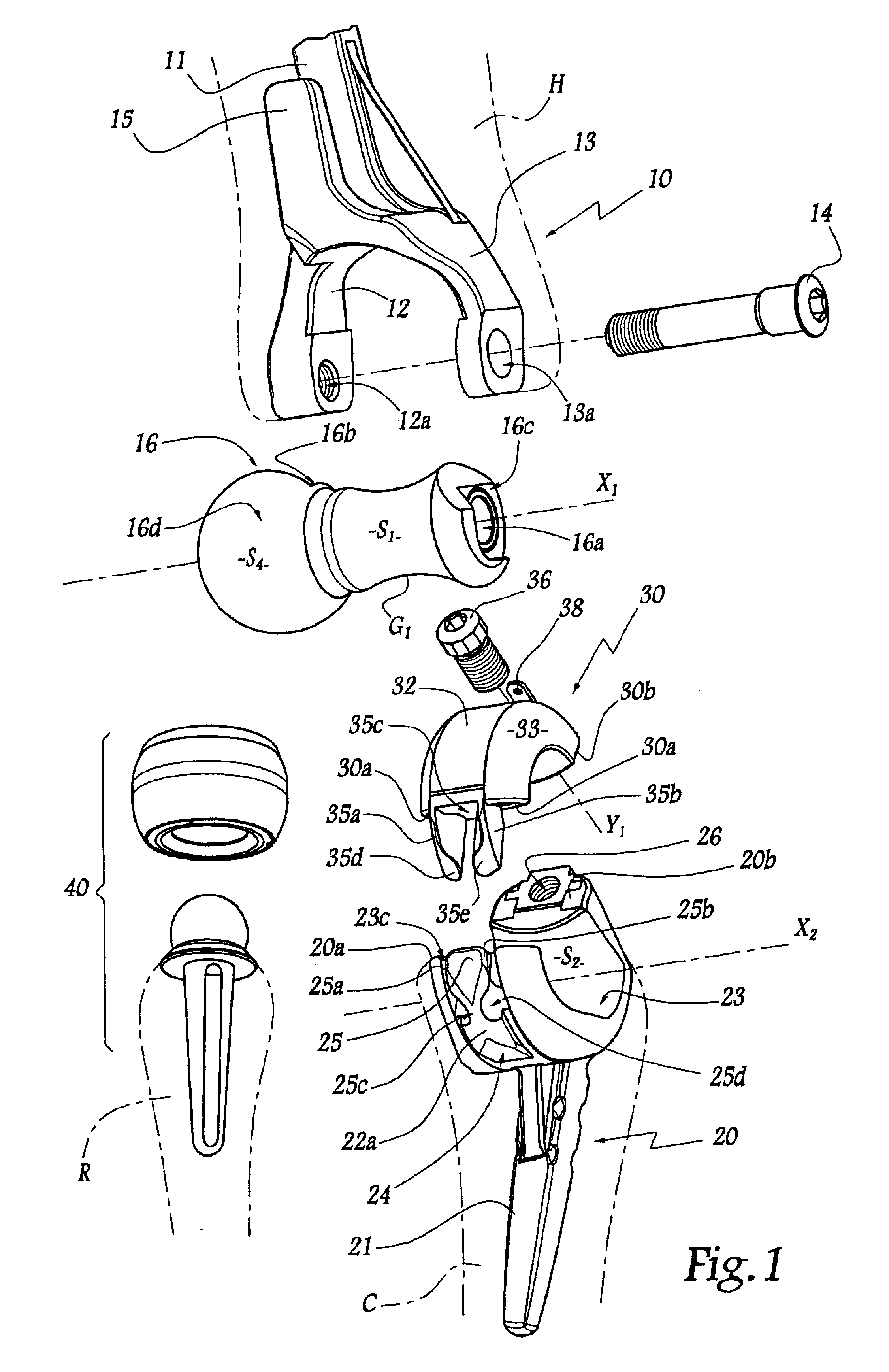
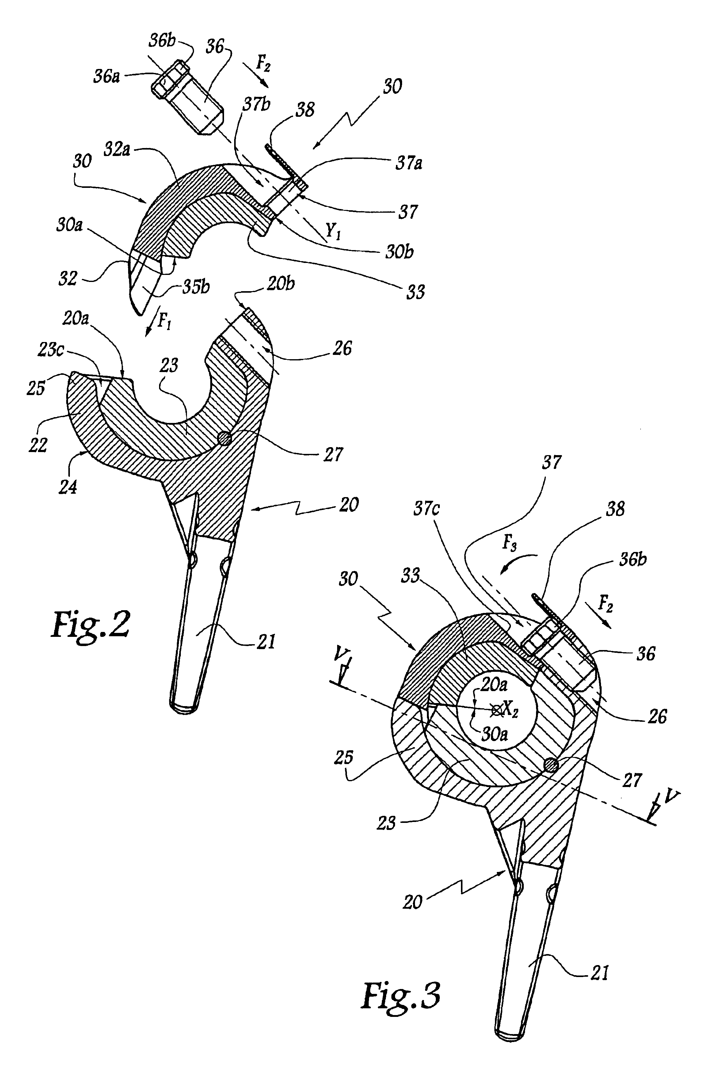
[0020]Referring now to the drawings, the prosthesis visible in FIGS. 1 to 3 comprises a humeral component 10 comprising a stem 11 intended to be driven in the medullary canal of a humerus H and extending in two branches 12 and 13, each pierced with an orifice 12a, 13a for passage of a hollow screw 14 forming pin. The hollow nature of the screw 14 allows the passage of suture yarns. The orifice 12a is tapped, allowing the screw 14 to be screwed. The stem 11 also extends in a third branch 15 intended to come into abutment against the cortex of the humerus.

[0021]An elongated piece 16 is provided with a central bore 16a whose dimensions are such as to receive the screw 14, this making it possible to mount the piece 16 between the branches 12 and 13. The piece 16 is provided with two end surfaces 16b and 16c provided to come respectively into contact with the opposite surfaces of the branches 12 and 13.

[0022]Between the surfaces 16b and 16c, the piece 16 is substantially cylindrical, wit...


PUM


Abstract

A humeral component, forming a first articulating surface, and an ulnar component forming a second articulating surface adapted to be disposed around a part of the first articulating surface and to pivot about its longitudinal axis. This ulnar component is provided with structure for mounting a locking element which forms a third articulating surface extending the second and adapted likewise to be disposed around a part of the first surface. These mounting structure comprise guiding structures adapted to cooperate with complementary structure provided on the locking element in order to guide this element in translation with respect to the ulnar component, up to a position where blocking structure provided respectively on the locking element and on the ulnar component may be employed to immobilize this element on this component, these blocking structure being able to be employed only in this position.

Description

[0001]This application claims the benefit of U.S. provisional application No. 60 / 473,446 filed May 28, 2003.FIELD OF THE INVENTION[0002]The present invention relates to an elbow prosthesis comprising at least one humeral component and one ulnar component.[0003]It concerns more particularly an elbow prosthesis of which the ulnar component is adapted to receive a locking element which forms an articulating surface extending that of the ulnar component, the articulating surfaces of the locking element and of the ulnar component being adapted to be arranged together around at least a part of another articulating surface belonging to a humeral component. A prosthesis of this type is known from EP-A-1 051 954.BACKGROUND OF THE INVENTION[0004]In such a prosthesis, the locking element is maintained in position on the ulnar component thanks to a screw introduced in a through housing in this element and tightened in a tapping provided on the ulnar component. It has proved in practice that the...

Claims


Application Information

Patent Timeline
Patent Type & Authority Patents(United States)
IPC IPC(8): A61F2/38
CPCA61F2/3804
Inventor TORNIER, ALAIN
Owner TORNIER SA SAINT ISMIER
Why Eureka
Try Eureka