Interferometric measurement device for determining the birefringence in a transparent object

a measurement device and transparent object technology, applied in measurement devices, instruments, scientific instruments, etc., can solve the problems of object, birefringent effect of optical components of measurement devices, and inability to separate from birefringent effect of objects, and the measurement accuracy of this known measurement device is therefore limited

Inactive Publication Date: 2007-05-01
CARL ZEISS SMT GMBH
View PDF6 Cites 0 Cited by
  • Summary
  • Abstract
  • Description
  • Claims
  • Application Information

AI Technical Summary

Benefits of technology

[0006]It is therefore a first object of the present invention to refine an interferometric measurement device of the type mentioned at the start, in such a way that spatially resolved analysis of the birefringence of the object is possible.
[0015]A positionally resolving measuring instrument, in which the positionally resolving measuring instrument is a CCD camera, provides sufficient positional resolution.
[0017]If the object and / or a component of the beam-shaping optical arrangement has the shape of a wedge, the creation of additional light beams which might interfere with the measurement is avoided.
[0018]If the device comprises at least one further optical component, which produces, in a calibration state of the interferometric measurement device in which the object is removed, a calibration light beam which is guided in such a way that it does not pass through the entire beam-shaping optical arrangement, and which is interferometrically superposed with a light beam that does pass through the entire beam-shaping optical arrangement, the measurement accuracy of the interferometric measurement device according to the invention is improved in such a way that a high absolute measurement accuracy of the birefringence of a specimen is achieved, even in the event of relatively large birefringence contributions from the interferometer components.

Problems solved by technology

Another problem with the measurement device according to DE 197 33 890 A1 is that the birefringent effects of the optical components of the measurement device, that is to say not of the object, cannot be separated from the birefringent effects of the object.
The measurement accuracy of this known measurement device is therefore limited by the birefringence of the optical components of the measurement device.
A spatially resolved birefringence measurement is not possible, or is only limitedly possible, with the measurement device according to DE 197 33 890 A1, which can provide only integral or, limited by the sections of the object which are acquired by means of the focused measurement beam, section-wise birefringence data of the object.

Method used


Image

  • Interferometric measurement device for determining the birefringence in a transparent object
  • Interferometric measurement device for determining the birefringence in a transparent object
  • Interferometric measurement device for determining the birefringence in a transparent object

Examples


Embodiment Construction

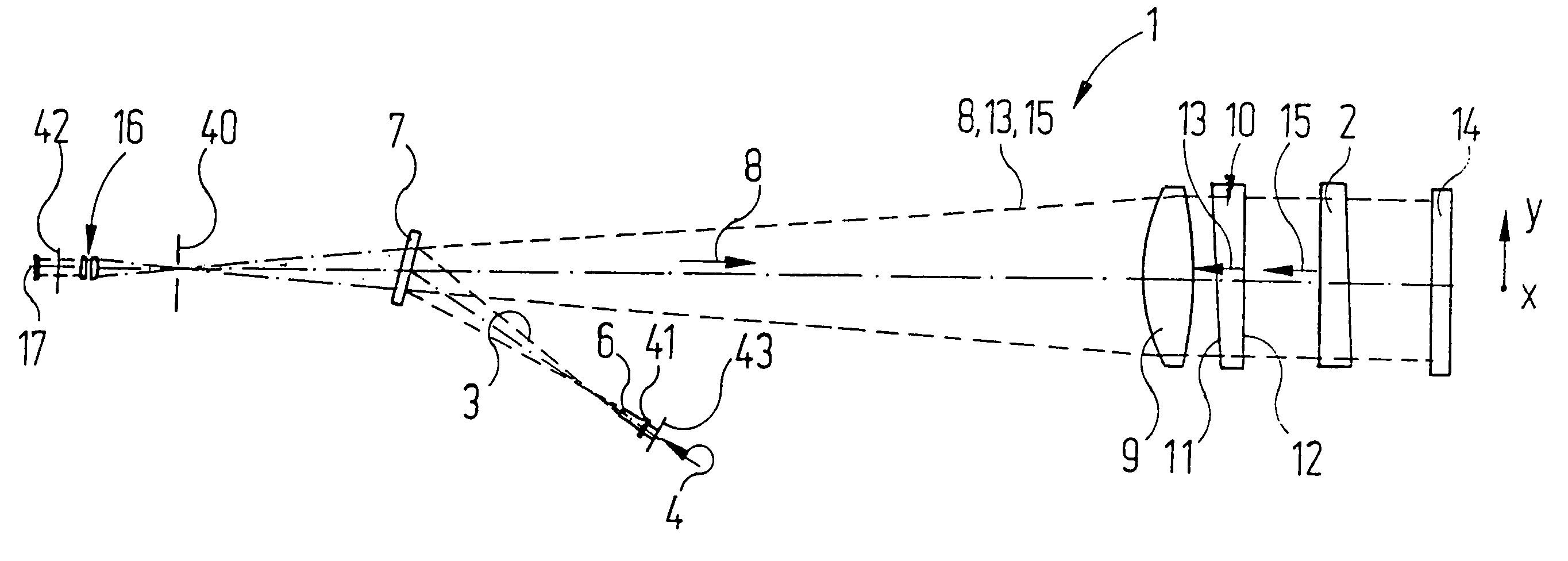
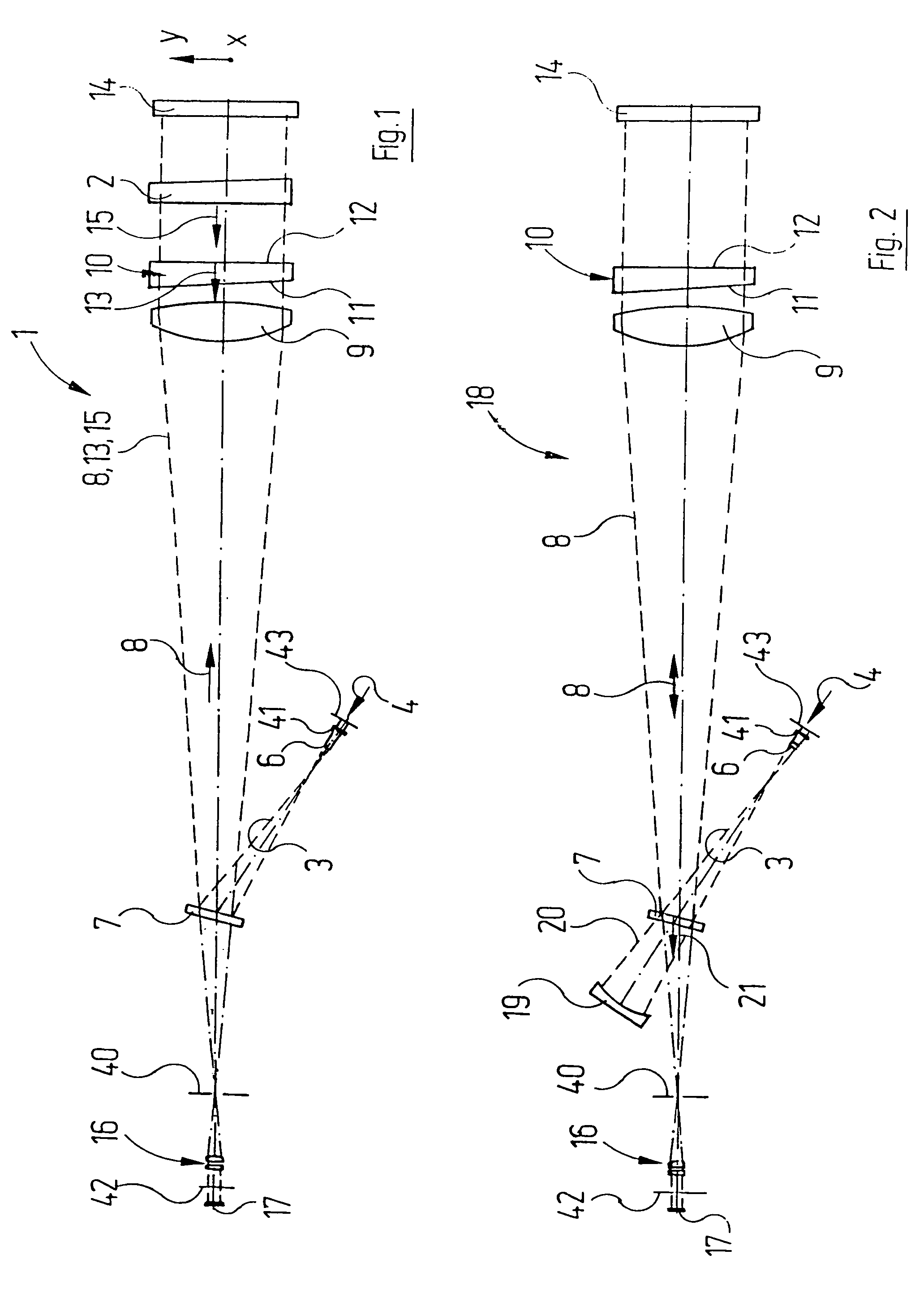
[0027]An interferometric measurement device 1 for spatially resolved determination of the birefringence, for example the stress birefringence, in a transparent specimen or object 2, for example in an optical blank for a lens of a projection illumination system for microlithography, is shown in FIG. 1 in a meridional section. A measurement light beam 3 is produced by a light source (not shown in the drawing), for example a helium-neon laser with a wavelength of 632.8 nm, and enters the interferometric measurement device 1 in the direction of the arrow 4 through a polarizer 43, which linearly polarizes the beam, and through through a half-wave plate 41. The half-wave plate 41 is mounted rotatably about an axis coinciding with the principal beam direction of the measurement light beam 3.

[0028]After passing through the half-wave plate 41, the measurement light beam 3 firstly passes through a lens 6 with positive refractive power for beam shaping. The measurement light beam 3 is in this ...


PUM


Abstract

An interferometric measurement device for determining the birefringence in a transparent object comprises an interferometer with an input for an input light beam. At an output of the interferometer an object light beam passing through the object interferometrically superposes with a reference light beam not passing through the object. A positionally resolving measuring instrument determines at the interferometer output a distribution of phase differences between the object light beam and the reference light beam over the beam cross section of the beams. The measurement device further includes an instrument for modifying the polarization state of the input light beam.

Description

FIELD OF THE INVENTION[0001]The invention relates to an interferometric measurement device for determining the birefringence in a transparent object.DESCRIPTION OF RELATED ART[0002]DE 197 33 890 A1, which corresponds to U.S. Pat. No. 6,172,752 B1, describes a low-coherence interferometric method for birefringence measurement of a transparent object in reflection by means of a Michelson interferometer. The object constitutes the end mirror of one interferometer arm. In order to measure the birefringence, the end mirror of the other interferometer arm is displaced along the optical axis in an oscillatory manner with a fixed frequency for phase modulation. At the same time, either the object or a converging lens focusing the measurement light onto it is displaced in the direction of the optical axis. Depending on the position of the object with respect to the converging lens, the optical path of a measurement beam through the object in the object interferometer arm changes, and this is...

Claims


Application Information

Patent Timeline
Patent Type & Authority Patents(United States)
IPC IPC(8): G01B9/02
CPCG01M11/0228G01N21/23
Inventor SCHULTE, STEFANGODECKE, UWE
Owner CARL ZEISS SMT GMBH
Why Eureka
Try Eureka