

Rotor arrangement for an electrical drive motor of a compressor, particularly a refrigerant compressor
a technology of electrical drive motor and compressor, which is applied in the direction of dynamo-electric machines, magnetic circuit rotating parts, magnetic circuit shape/form/construction, etc., can solve the problems of saving time and cost during mounting, and achieve the effect of ensuring good concentric run of the motor, sufficient position tolerance, and sufficient accuracy
- Summary
- Abstract
- Description
- Claims
- Application Information
AI Technical Summary
Benefits of technology
Problems solved by technology
Method used
Image

Examples
Embodiment Construction
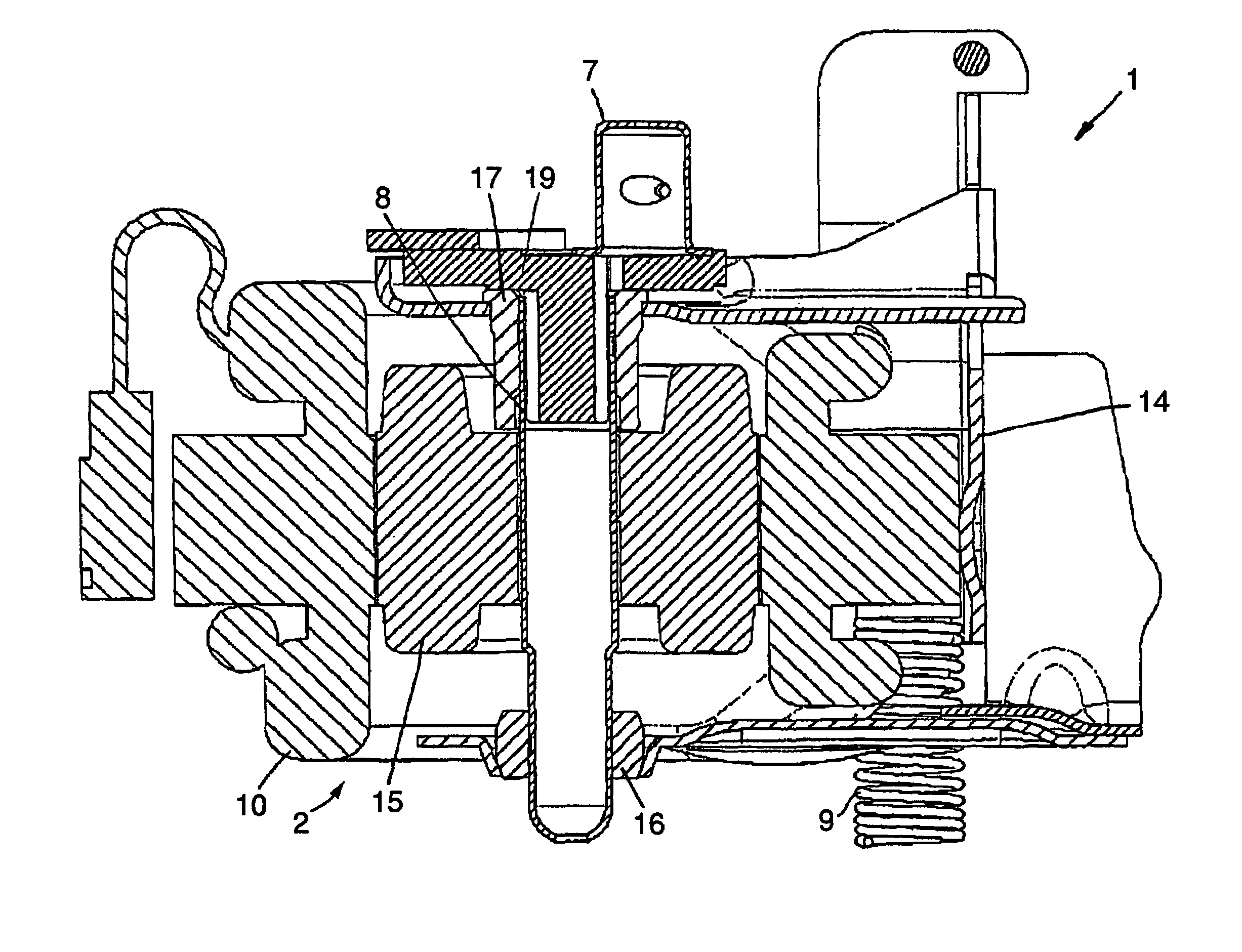
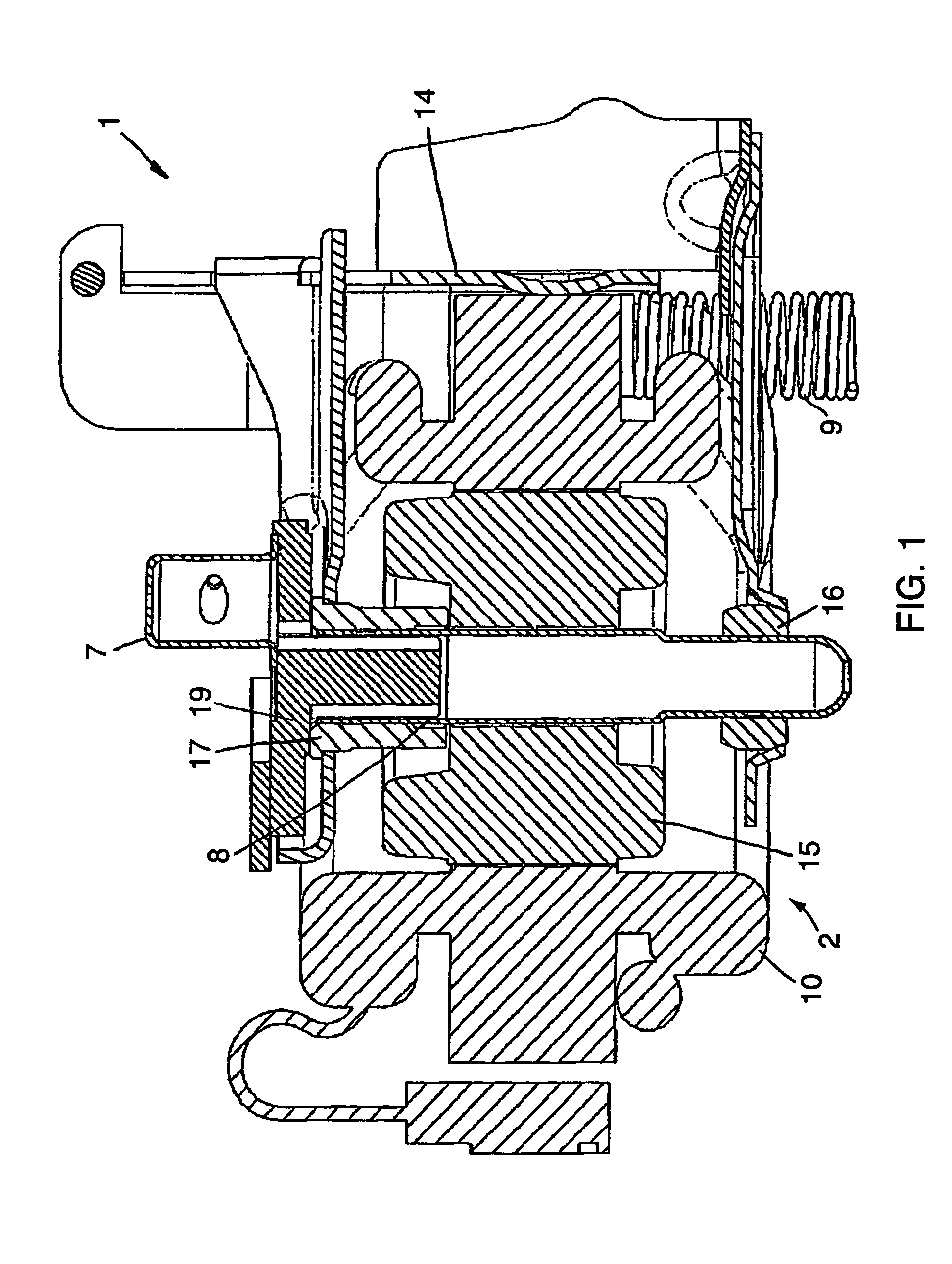
[0025]FIG. 1 shows a schematic view of a refrigerant compressor, which has an electrical drive motor 2. The drive motor 2 drives a compressor, not shown in detail, which has, in a manner known per se, a cylinder, in which a piston reciprocates. Via a connecting rod, the piston is connected with a crank pin 7 of a drive shaft 8. Via springs 9, the complete refrigerant compressor 1 is connected with a hermetic compressor housing, not shown in detail. Such refrigerant compressors are frequently used in household refrigeration appliances.
[0026]When the shaft 8 turns, its turning movement is converted to a reciprocating movement of the piston by the crank pin 7.
[0027]The motor 2 has a stator 10, which supports a compressor block 14, on which the compressor is mounted. The stator 10 surrounds a rotor 15, which is unrotatably connected with the shaft 8. The shaft 8 is arranged to be vertical. On both sides of the motor 2 the shaft 8 is radially supported by a lower bearing element 16 and a...
PUM
 Abstract
Description
Claims
Application Information