Optical interposer

Inactive Publication Date: 2012-07-26
TE CONNECTIVITY CORP
View PDF2 Cites 13 Cited by
  • Summary
  • Abstract
  • Description
  • Claims
  • Application Information

AI Technical Summary

Benefits of technology

[0010]In one embodiment, the air gap between the reflective surface and the fiber/planar waveguide end face is reduced by configuring the fiber/planar waveguide end face with a corresponding mating facet having essentially the same angle as the reflective facet at the terminal end of the groove. This way, when the fiber/planar waveguide is disposed in the interposer groove, the facets of the substrate and fiber/planar waveguide end face mechanically contact each other. Additional contacting or non-contacting facets may be added to the interposer optical coupling mirror and fiber/planar waveguide end face to improve optical coupling.
[0011]In o

Problems solved by technology

Therefore, current devices utilizing the end face mirror of the groove to launch light through an end of the optical fiber cause much of the light to be reflected away from the axis of the optical fiber resulting in non-optimal signal transmission

Method used


Image

  • Optical interposer
  • Optical interposer
  • Optical interposer

Examples


Example

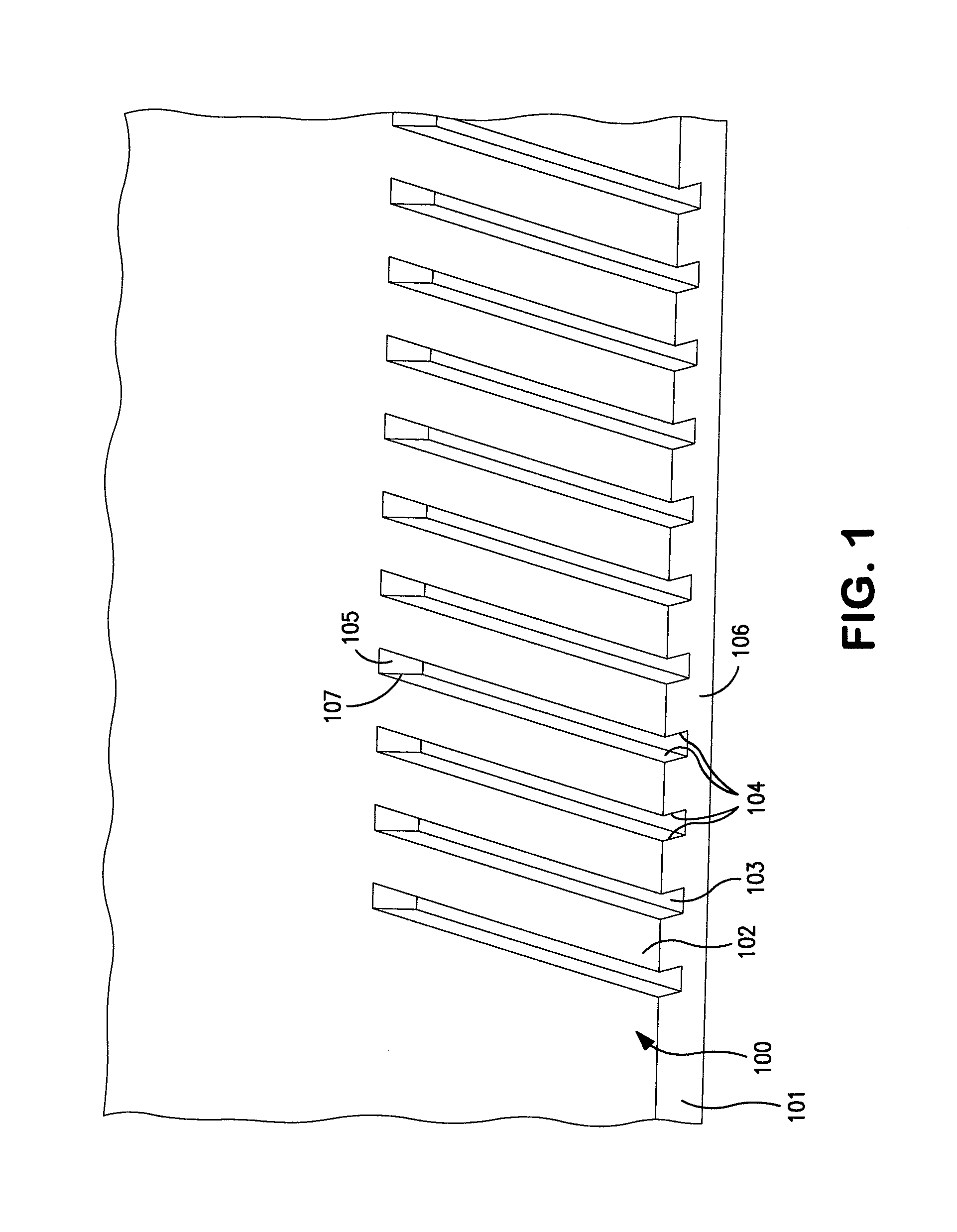
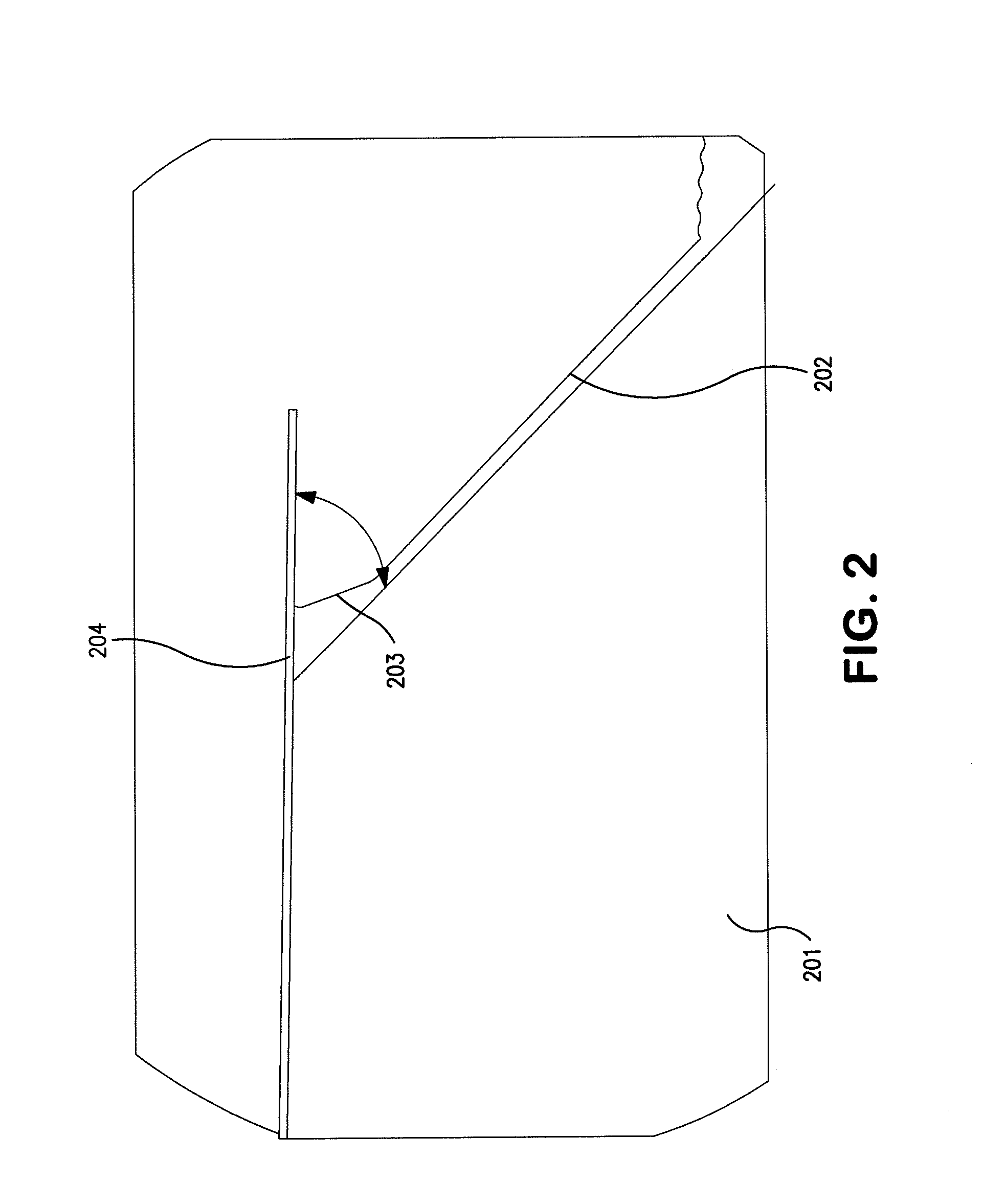
[0026]Referring to FIG. 1, one embodiment of an optical interposer 100 of the present invention is shown. The optical interposer 100 comprises a substrate 101 having a top planar surface 102 and at least one groove 103 defined in the top planar surface, extending from an edge 106 of the substrate to a terminal end 107. The groove 103 has side walls 104 and a first facet 105 at the terminal end, which is essentially perpendicular to side walls. The first facet is configured at a first angle α relative to the top planar surface. A reflective coating (not shown) is deposited on the first facet 105. Each of these elements and alternative embodiments are described in greater detail below.

[0027]A primary function of the interposer is to provide a substrate or backbone to support and secure an optical conduit, optical component(s) and supporting electrical circuitry. As used herein, an optical conduit refers to any know medium for facilitating the propagation of optical signal in a certain...


PUM


Abstract

An optical interposer comprising: (a) a substrate having a planar surface: (b) at least one groove defined in the planar surface and extending from an edge of the substrate to a terminal end, the groove having side walls and a first facet at the terminal end perpendicular to side walls, the facet having a first angle relative to the planar surface, the first angle being about 45 degrees; and (c) a reflective coating on the first facet.

Description

FIELD OF INVENTION[0001]The subject matter herein relates generally to fiber optic substrates, and more particularly, to an interposer with optical coupling and alignment features.BACKGROUND OF INVENTION[0002]Fiber optics are used in a wide variety of applications. The use of optical fibers as a medium for transmission of digital data (including voice, internet and IP video data) is becoming increasingly more common due to the high reliability and large bandwidth available with optical transmission systems. Fundamental to these systems are optical subassemblies for transmitting and / or receiving optical signals.[0003]Optical subassemblies typically comprise an interposer. As used herein, an interposer functions as a substrate for optical, opto-electrical, and electrical components and provides interconnections to optically and / or electrically interconnect the optical / opto-electrical / electrical components. For example, a typical interposer may comprise a substrate, for example, silico...

Claims


Application Information

Patent Timeline
IPC IPC(8): G02B6/122G02B6/132G02B6/00G02B6/136
CPCG02B6/4249G02B6/4214
Inventor BOWEN, TERRY PATRICKMILLER, RICHARD DEAN
Owner TE CONNECTIVITY CORP
Why Eureka
Try Eureka