Modularized interposer

a module-based, interposer technology, applied in the field of optical coupling, can solve the problems of compound optical couplings increasing exponentially the complexity of manufacturing the interposer, and achieve the effects of simplifying the manufacture of components, increasing exponentially the complexity of manufacturing, and facilitating passive alignmen

Active Publication Date: 2013-09-05
TYCO ELECTRONICS LOGISTICS AG (CH)
View PDF13 Cites 33 Cited by
  • Summary
  • Abstract
  • Description
  • Claims
  • Application Information

AI Technical Summary

Benefits of technology

[0008]The present invention relates to an interposer having separate and discrete components for accommodating the lenses and the fibers. Applicant recognizes that configuring an interposer to optically couple lenses and fibers which have perpendicular optical axes involves multiple optical alignments, each compounding the complexity of the interposer. That is, a traditional interposer optically couples the opto-electric devices (OEDs) to lenses and lenses to fibers in a serial fashion. The compound optical couplings increase exponentially the complexity of manufacturing the interposer. By segregating the interposer into a discrete lens component and a discrete fiber component, the compounded optical couplings in a single component can be eliminated, thereby significantly simplifying the components manufacture.
[0009]Modularizing the interposer into discrete components also has other benefits depending on the embodiment of the invention. For example, such a configuration lends itself to alignment features that facilitate passive alignment. Specially, in one embodiment in which the reflective surface is defined in the fiber component, the lens component may be passively aligned on the substrate by aligning the lenses over the OEDs because the lenses are not obscured by the reflective surface. Furthermore, in one embodiment, because the optical coupling between the lens / fiber and the OED / lens are split, the components can be molded as parallel layers, making their interface simple and relatively easy to align.
[0010]The modular design also facilitates manufacturability. One aspect of the improved manufacturability is the enhanced ability to inspect the molds and the molded components. Specifically, in an embodiment in which the lens and fiber components are parallel, the molds pull from opposing sides, and the critical features (e.g., lenses, fiducials, alignment features) are located on just one side of the mold, thereby making it easier for the mold vendor to inspect the molds, and for the user to inspect the molded pieces. In this respect, the modular design also allows the different components to be tested separately and defects to be detected earlier in the assembly process such that correction action may be taken or the part scrapped without additional investment of manufacturing time and expense.
[0011]Yet another benefit of the modular design is the potential for enhanced performance. For example, in one embodiment, the optical beam is expanded in the interposer at the interface between the lens and fiber components, making the beam more robust and less susceptible to dust and slight misalignments.
[0012]The modular design also provides for a more robust package. For example, in one embodiment, the area of the lens component can be as large as a glass plate increasing the adhesive bonding force.

Problems solved by technology

The compound optical couplings increase exponentially the complexity of manufacturing the interposer.

Method used


Image

  • Modularized interposer
  • Modularized interposer
  • Modularized interposer

Examples


Embodiment Construction

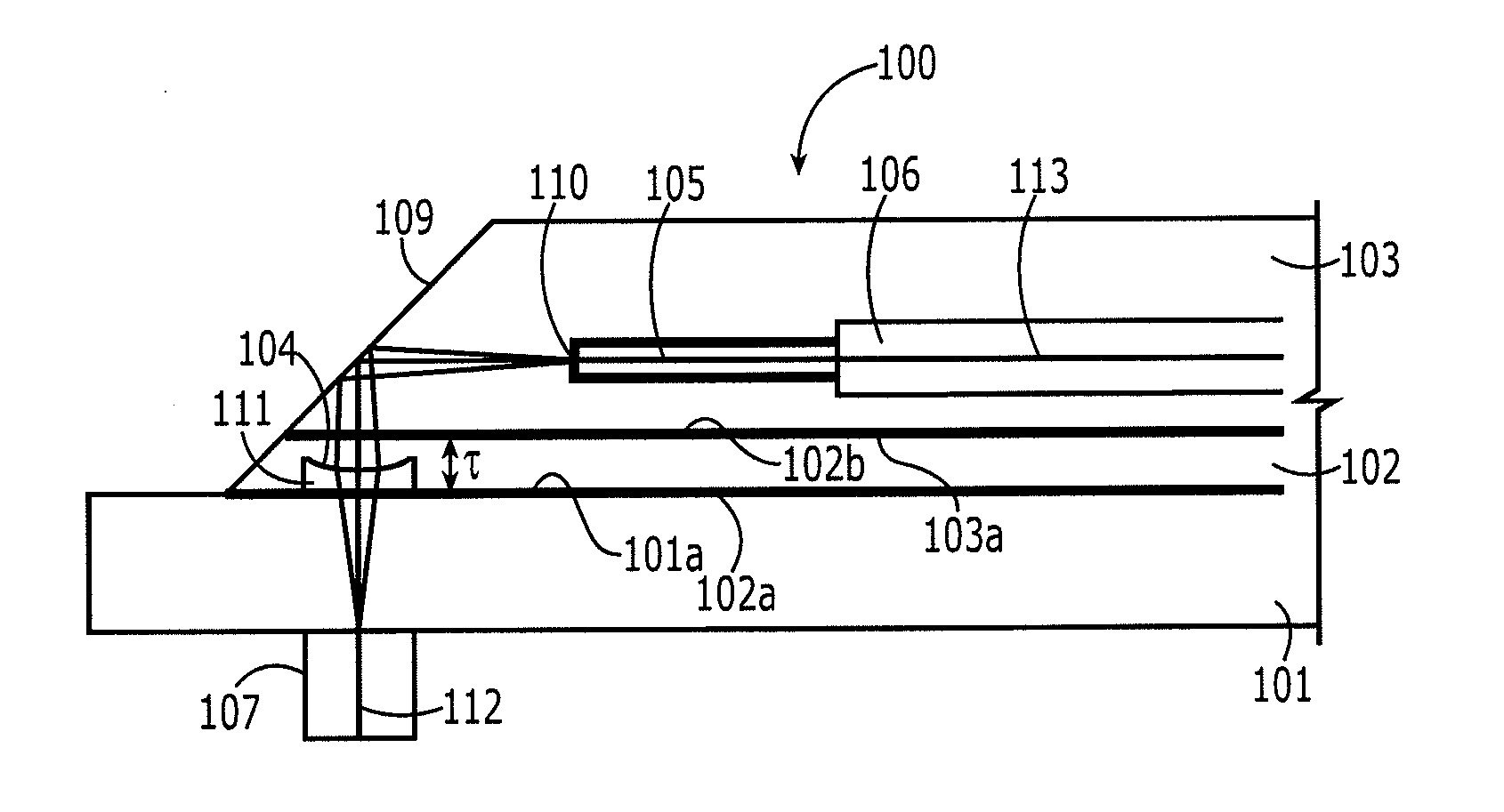
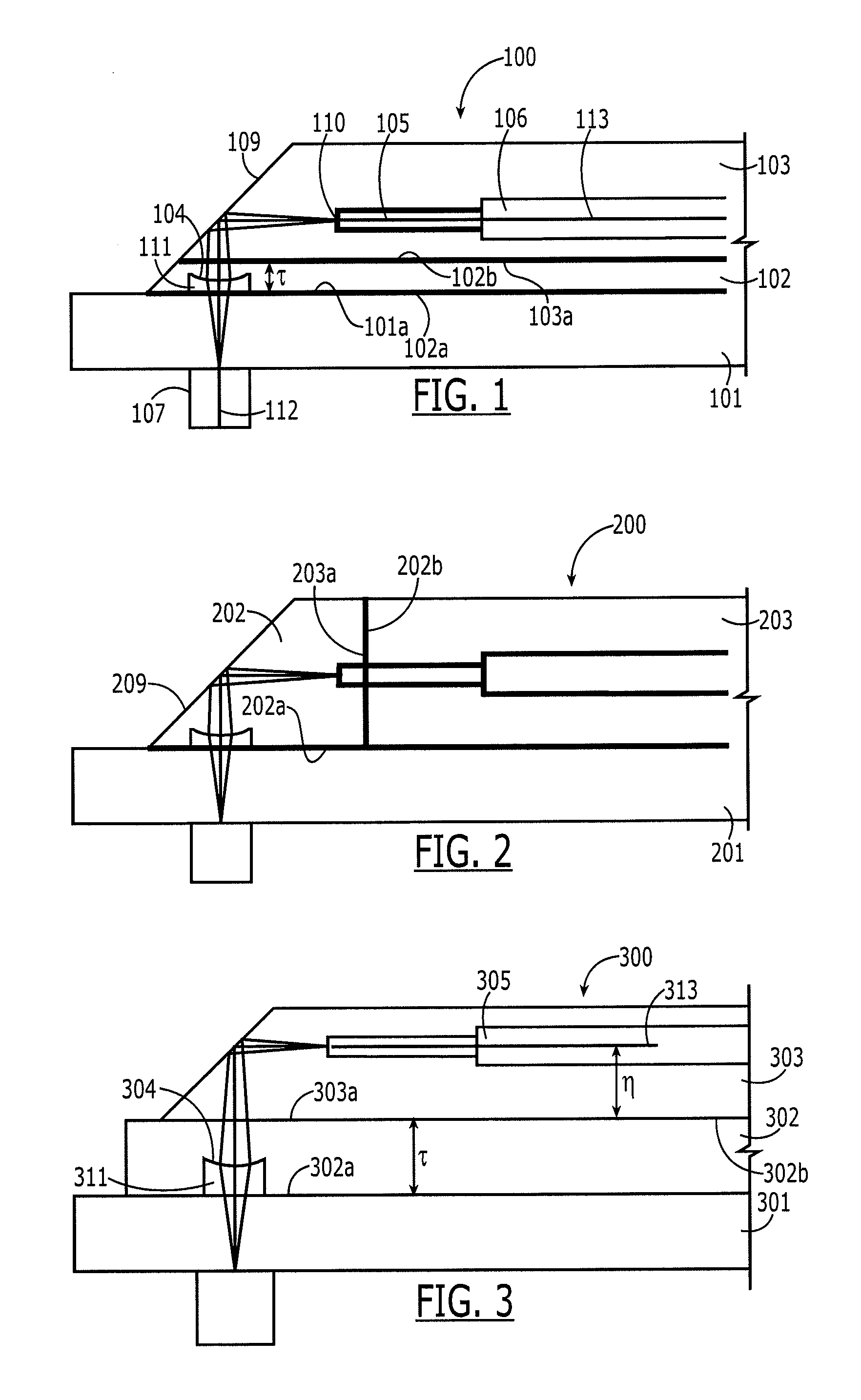
[0028]Referring to FIG. 1, one embodiment of the interposer 100 of the present invention is shown. As shown, the interposer 100 optically couples the optical device 107 to a fiber 106. The optical device 107 is mounted on a substrate 101. The interposer comprises a lens component 102 comprising at least one lens 104 defined by a cavity 111 for optically coupling with the OED 107. The lens has a first optical axis 112 essentially perpendicular to the substrate 101. The lens component 102 also has first surface 102a for mating with a top surface 101a of the substrate 101, and a second surface 102b for mating with a third surface 103a of a fiber component 103. The fiber component 103 comprises the third surface 103a and a cavity 105 for receiving at least one fiber 106 and holding the fiber along a second optical axis 113. The first and second optical axes are essentially perpendicular. At least one of the lens component 102 or the fiber component 102 comprises a reflective surface 109...


PUM


Abstract

An interposer for optically coupling an optical device (OD) to a fiber, the OD mounted on a substrate, the interposer comprising: (a) a lens component comprising at least one lens for optically coupling with the OD the lens having a first optical axis, a first surface for mating with the substrate, and a second surface for mating with a third surface of a fiber component; (b) the fiber component comprising the third surface and a cavity for receiving at least one fiber and holding the fiber along a second optical axis, the first and second optical axes being perpendicular; and (c) wherein at least one of the lens component or the fiber component comprises a reflective surface for optically coupling the lens to a point along the second optical axis and adjacent the cavity.

Description

FIELD OF INVENTION[0001]The present invention relates, generally, to an optical coupling between optical components and waveguides / fibers and, more specifically, to an interposer for active cable assemblies for optically coupling optoelectric devices to fibers.BACKGROUND OF INVENTION[0002]Active cable assemblies are gaining in popularity as a way of exploiting the broad bandwidth capability of optical fiber. As used herein, an active cable assembly is an optical cable in which the circuitry for converting between electrical and optical is on either side of the optical cable. Thus, the electrical to optical conversion is performed within the cable assembly itself. Significant performance improvements especially with respect to maximum cable length maybe achieved using an active cable assembly.[0003]A critical component of an active cable assembly is the interposer, which optically couples an opto-electric device (OED) to a fiber in the cable assembly. Generally, although not necessar...

Claims


Application Information

Patent Timeline
Patent Type & Authority Applications(United States)
IPC IPC(8): G02B6/32
CPCG02B6/4204G02B6/4292G02B6/4249G02B6/4214
Inventor KADAR-KALLEN, MICHAEL AARON
Owner TYCO ELECTRONICS LOGISTICS AG (CH)
Why Eureka
Try Eureka