Brushless motor

A motor and core technology, applied in the magnetic circuit shape/style/structure, electromechanical devices, magnetic circuit rotating parts, etc., can solve problems such as poor steering feel, reduce the air gap, reduce the cogging torque, The effect of low cogging torque

Inactive Publication Date: 2017-05-24
MITSUBA CORP
View PDF4 Cites 13 Cited by
  • Summary
  • Abstract
  • Description
  • Claims
  • Application Information

AI Technical Summary

Problems solved by technology

[0003] On the other hand, in the EPS system, if the cogging torque of the motor increases, there is a problem that the steering feeling when the power is not energized becomes poor.

Method used


Image

  • Brushless motor
  • Brushless motor
  • Brushless motor

Examples


Embodiment Construction

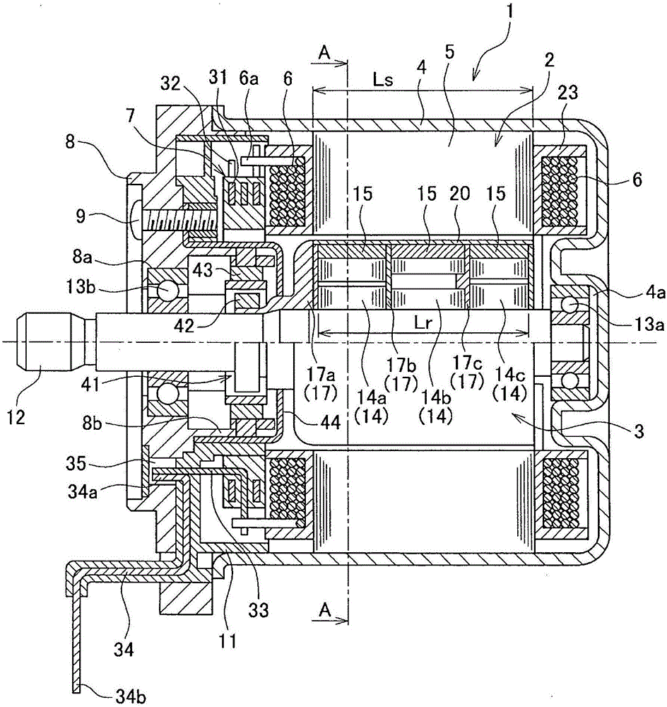
[0027] Hereinafter, embodiments of the present invention will be described in detail based on the drawings. An object of the following embodiments is to provide a brushless motor with high torque and low cogging torque that minimizes the reduction in torque and reduces the cogging torque.

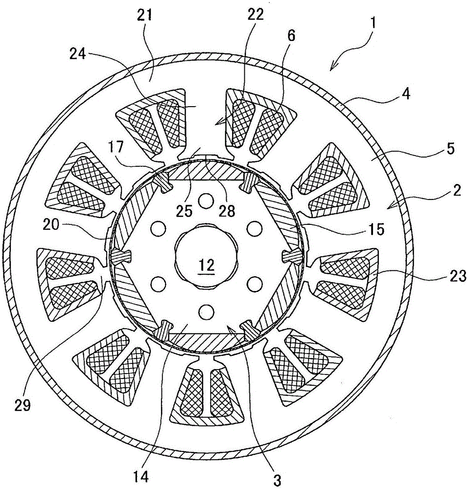
[0028] figure 1 It is a cross-sectional view showing the structure of a brushless motor 1 (hereinafter abbreviated as motor 1 ) according to one embodiment of the present invention. figure 2 is along figure 1 Sectional view of line A-A. The motor 1 is used, for example, as a power source of a steering column assist type EPS, rotates forward and reverse according to a handle operation direction, and applies motion assist force to a steering shaft of an automobile. Such as figure 1 As shown, the motor 1 has an inner rotor type structure in which a stator (fixed body) 2 is arranged on the outside and a rotor (rotating body) 3 is arranged on the inside. The motor 1 is attached to an unill...


PUM


Abstract

In the present invention, each tooth (22) has a tooth body part (24) and a tooth tip part (25). A pair of slant parts (26) project from both circumferential sides of the tooth tip part (25). A tip surface (27) is formed on the inner diameter-side end surface of the tooth tip part (25) so as to face a magnet (15) across an air gap (g). A recessed groove part (28) extending in an axial direction is disposed at the center of the tip surface (27). The depth (d) of the groove part (28) is set in the range of 0 < d <= (Lx-Rt) / 3, and the width (Wg) is set in the range of Wt > Wg >= Wt / 2 (Lx: distance from the center of a rotor to a tooth-slant intersection (X), which is the intersection of an extended line (P) from a circumferential side surface of the tooth body and an extended line (Q) from the slant surface of the slant part; Rt: radius of the inner diameter of the tooth tip surface; Wt: width of the tooth body).

Description

technical field [0001] The present invention relates to a high-torque, low-cogging brushless motor, and in particular, to a brushless motor suitable for use as a drive source of an electric power steering device. Background technique [0002] In order to assist the steering force of automobiles and the like, in recent years, many vehicles have been equipped with so-called power steering devices. As power steering devices, in recent years, electric power steering devices (so-called electric power steering devices: EPS) using electric motors as a driving source have been increasing in view of engine load reduction and weight reduction. A motor as a power source of an electric power steering apparatus requires complicated control, but a brushless motor is desired for ease of maintenance. Recently, EPS systems using brushless motors are becoming mainstream as control elements and controllers have become more functional. [0003] On the other hand, in the EPS system, if the cog...

Claims


Application Information

Patent Timeline
Patent Type & Authority Applications(China)
IPC IPC(8): H02K1/14H02K1/16H02K1/22H02K1/27H02K21/16
CPCH02K21/16H02K1/146H02K2201/03H02K2213/03H02K1/278H02K1/16H02K21/14
Inventor 池野弘达青木孝将小川佑弥
Owner MITSUBA CORP
Why Eureka
Try Eureka