Magnetically-coupled valve

a magnetic coupling and valve body technology, applied in the field of magnetic valves, can solve the problems of reducing the efficiency of the magnetic coupling sought, reducing the performance increasing the cost price of such a valve, so as to achieve efficient and reliable control over time

Inactive Publication Date: 2010-06-01
SAMES KREMLIN
View PDF12 Cites 13 Cited by
  • Summary
  • Abstract
  • Description
  • Claims
  • Application Information

AI Technical Summary

Benefits of technology

[0005]Owing to the invention, the material of the needle constitutes the induced poles of a magnetic coupling device whose magnetic bodies form the inducing poles. The manufacturing tolerances of the needle enable a narrower air gap to be used than when magnets are mounted on the needle. Advantageously, the needle is equipped with ribs formed from a magnetic material. The positioning and the geometry of those ribs are preferably adapted as a function of the positioning and the geometry of the polar masses constituted by the magnetic bodies. In particular, the thickness of the ribs may be substantially equal to the thickness of the magnetic bodies. Likewise, the relative spacing of the ribs may be substantially equal or correspond substantially to a multiple or a sub-multiple of the relative spacing of the magnetic bodies. The distribution and the geometry of the ribs of the needle permit a concentration of the magnetic flux at their location, and hence improved magnetic coupling between the needle and the actuating device.
[0008]the ribs are unitary with the body of the needle, which is particularly economical and enables them to be manufactured by machining, with a high degree of precision;
[0009]the volume between two adjacent ribs is packed with a non-magnetic filling material, which prevents the accumulation of product passing through the valve, for example a coating product, between two ribs;
[0014]Such an installation permits efficient and reliable control over time of the amounts of coating product(s) and / or cleaning product(s) supplied to a projector. In such an installation, a valve according to the invention may also be used as a pressure regulator.

Problems solved by technology

The mounting of permanent magnets on the needle is a tricky operation which requires particular care of a kind which substantially increases the cost price of such a valve.
This large air gap reduces the efficiency of the magnetic coupling sought.
In addition, the magnets mounted on the needle are susceptible to attack by the fluid passing through the valve, and hence there is a risk of deterioration by abrasion and / or corrosion which may result in a decrease in the performance of such a valve.

Method used


Image

  • Magnetically-coupled valve
  • Magnetically-coupled valve
  • Magnetically-coupled valve

Examples


first embodiment

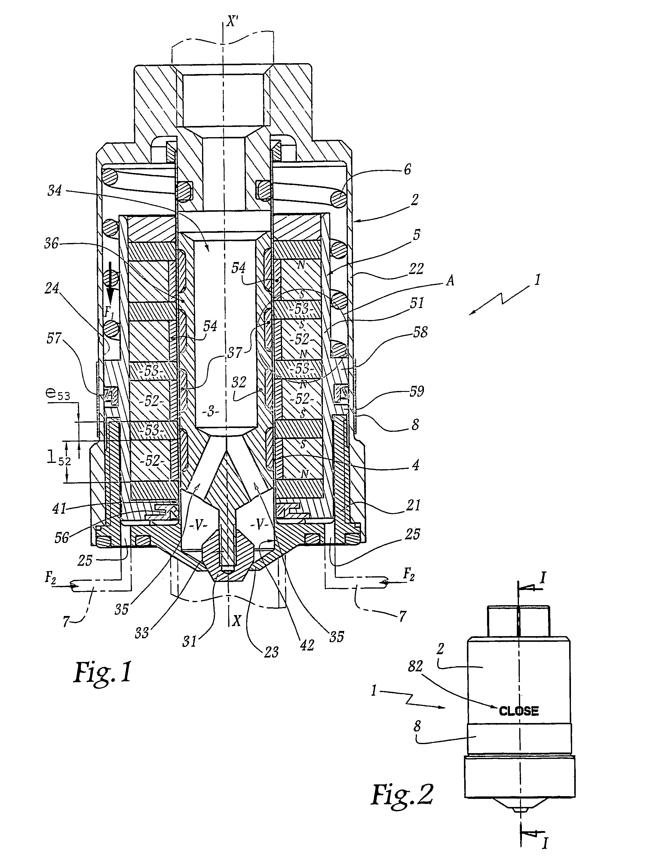
[0072]A ring 508 of the same-type as the ring 8 of the first embodiment can be mounted outside the casing 502 and coupled magnetically to the device 505 in order to indicate the position of the device 505 and the needle 503. The ring 508 is mobile between two end positions and can take up various intermediate positions as a function of the degree of opening of the valve 501. A graduation may be provided on the casing 502 in order to facilitate the noting of the position of the ring 508.

[0073]The valve 601 represented in FIG. 12 may also be regarded as a tap, of which the needle 603, the sealed partition 604 and the actuating device 605 are similar to those shown in FIGS. 6 and 7. In this embodiment, the device 605 is fixedly joined to a push-button 609 on which a user can exert a force F3 which permits the displacement of the push-button 605 and the needle 603 against a return force generated by a spring 606. The valve 605 is a tap which can be operated simply by pressing.

second embodiment

[0074]As shown in FIG. 13, a valve 701 described above may be integrated in a line 1001 for the supply of coating product to a coating product projector P which may be of any known type, electrostatic or non-electrostatic, manual or automatic. A flow or pressure sensor 1002 is connected to a regulating unit 1003 which controls a source 1007 for the supply of compressed air to the valve 701.

[0075]As shown in FIG. 14, a valve 801 according to the first embodiment may also be used in an installation comprising a line 1001, a sensor 1002, a regulating unit 1003 and a source 1007 of pressurized air.

[0076]The invention has been represented with magnetic valves of the two-way type. It is, however, applicable to three-way valves by making modifications that are within the competence of the person skilled in the art.

[0077]The invention is independent of the exact number of magnets carried by the actuating device. In fact, that number is chosen as a function of the intensity of the coupling ...


PUM


Abstract

The invention relates to a valve (1), comprising a body (2), within which a needle (3) moves, which can rest with sealing against a seat (23), fixed to the body (2). The needle (3) is magnetically coupled to an actuator body (5), across a closed and a magnetic chamber (4) provided with several magnets (52) between which magnetic bodies (53) are interspersed. The needle (3) has no magnets and is provided with ribs (36) made from a magnetic material. According to the invention, an improved magnetic coupling may be achieved, whereby the thickness and the relative separation of the ribs (36) are largely equal to the thickness (e53) and the relative separation (l52) of the magnetic bodies (53).

Description

FIELD OF THE INVENTION[0001]The invention relates to a magnetic valve and to an installation for projecting coating product, which comprises, inter alia, such a valve.BACKGROUND OF THE INVENTION[0002]It is known, for example, from EP-A-0-997-676 or from U.S. Pat. No. 4,940,207, to produce a valve whose needle is actuated by magnetic coupling through a sealed partition, which enables the product passing through the valve to be separated physically from the control means without using a seal susceptible to degradation, in particular owing to wear by abrasion and / or corrosion. In known valves, the needle is equipped with permanent magnets which are to cooperate with permanent magnets carried by an actuating device in order together to constitute magnetic coupling means. The mounting of permanent magnets on the needle is a tricky operation which requires particular care of a kind which substantially increases the cost price of such a valve. The manufacturing and fitting tolerances of pe...

Claims


Application Information

Patent Timeline
Patent Type & Authority Patents(United States)
IPC IPC(8): F16K31/08
CPCF16K31/086
Inventor MERABET, DJAMELPRUS, ERICBALLU, PATRICK
Owner SAMES KREMLIN
Why Eureka
Try Eureka